
Page 184 - Chalcogenide Glasses for Infrared Optics
P. 184
160 Cha pte r Se v e n
Pressure
gauge Forming gas
Furnace Stainless steel
pressure chamber
Glass cylinder
Thermocouple
and Laser
temperature
micrometer
controller
90.25
Heated, split-die
cladding glass
Heated, split-die
plastic coating
Spooler
Traverse
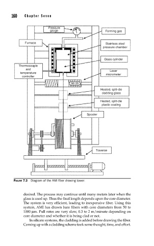
FIGURE 7.3 Diagram of the AMI fi ber drawing tower.
desired. The process may continue until many meters later when the
glass is used up. Thus the final length depends upon the core diameter.
The system is very efficient, leading to inexpensive fiber. Using this
system, AMI has drawn bare fibers with core diameters from 50 to
1000 µm. Pull rates are very slow, 0.3 to 2 m/minute depending on
core diameter and whether it is being clad or not.
In silicate systems, the cladding is added before drawing the fiber.
Coming up with a cladding scheme took some thought, time, and effort.