
Page 185 - Chalcogenide Glasses for Infrared Optics
P. 185
Glass Pr ocesses for Other Applications 161
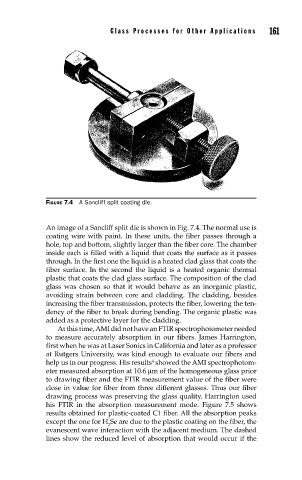
FIGURE 7.4 A Sancliff split coating die.
An image of a Sancliff split die is shown in Fig. 7.4. The normal use is
coating wire with paint. In these units, the fiber passes through a
hole, top and bottom, slightly larger than the fiber core. The chamber
inside each is filled with a liquid that coats the surface as it passes
through. In the first one the liquid is a heated clad glass that coats the
fiber surface. In the second the liquid is a heated organic thermal
plastic that coats the clad glass surface. The composition of the clad
glass was chosen so that it would behave as an inorganic plastic,
avoiding strain between core and cladding. The cladding, besides
increasing the fiber transmission, protects the fiber, lowering the ten-
dency of the fiber to break during bending. The organic plastic was
added as a protective layer for the cladding.
At this time, AMI did not have an FTIR spectrophotometer needed
to measure accurately absorption in our fibers. James Harrington,
first when he was at Laser Sonics in California and later as a professor
at Rutgers University, was kind enough to evaluate our fibers and
4
help us in our progress. His results showed the AMI spectrophotom-
eter measured absorption at 10.6 µm of the homogeneous glass prior
to drawing fiber and the FTIR measurement value of the fiber were
close in value for fiber from three different glasses. Thus our fiber
drawing process was preserving the glass quality. Harrington used
his FTIR in the absorption measurement mode. Figure 7.5 shows
results obtained for plastic-coated C1 fiber. All the absorption peaks
except the one for H Se are due to the plastic coating on the fiber, the
2
evanescent wave interaction with the adjacent medium. The dashed
lines show the reduced level of absorption that would occur if the