
Page 207 - Chalcogenide Glasses for Infrared Optics
P. 207
IR Imaging Bundles Made fr om Chalcogenide Glass Fibers 183
a thin sheet of Teflon on which all the ribbons are wound. After the drum
has been covered with ribbons, the fibers in each ribbon in a small area
are pushed together until touching. A small amount of a thin epoxy is
painted on the area to fuse the fibers. After short fused areas on all the
ribbons have been made, the Teflon film is removed from the drum with-
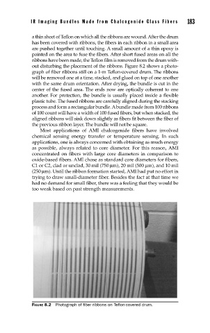
out disturbing the placement of the ribbons. Figure 8.2 shows a photo-
graph of fiber ribbons still on a 1-m Teflon-covered drum. The ribbons
will be removed one at a time, stacked, and glued on top of one another
with the same drum orientation. After drying, the bundle is cut in the
center of the fused area. The ends now are optically coherent to one
another. For protection, the bundle is usually placed inside a flexible
plastic tube. The fused ribbons are carefully aligned during the stacking
process and form a rectangular bundle. A bundle made from 100 ribbons
of 100 count will have a width of 100 fused fibers, but when stacked, the
aligned ribbons will sink down slightly as fibers fit between the fiber of
the previous ribbon layer. The bundle will not be square.
Most applications of AMI chalcogenide fibers have involved
chemical sensing energy transfer or temperature sensing. In such
applications, one is always concerned with obtaining as much energy
as possible, always related to core diameter. For this reason, AMI
concentrated on fibers with large core diameters in comparison to
oxide-based fibers. AMI chose as standard core diameters for fibers,
C1 or C2, clad or unclad, 30 mil (750 µm), 20 mil (500 µm), and 10 mil
(250 µm). Until the ribbon formation started, AMI had put no effort in
trying to draw small-diameter fiber. Besides the fact at that time we
had no demand for small fiber, there was a feeling that they would be
too weak based on past strength measurements.
FIGURE 8.2 Photograph of fi ber ribbons on Tefl on-covered drum.