
Page 208 - Chalcogenide Glasses for Infrared Optics
P. 208
184 Cha pte r Ei g h t
8.2 IR Imaging Bundles of 1-m Length
1
In the first attempts to make a bundle with C1 glass, the ribbons were
only 0.5 m long and made with relatively coarse unclad fiber, 20 mil,
10 mil, and 4 mil. The AMI fiber drawing process was very slow when
cladding with glass, so the low-viscosity polyamide plastic coating was
used instead. The index of C1 was 2.8 while the index of the polyamide
plastic was 1.4 and thus would serve as cladding. At this point the only
infrared camera AMI had to use for image evaluation was a pyroelectric
vidicon camera sensitive in the 8- to 12-µm band. The camera was imaged
through a good-quality FLIR module and was connected to a TV moni-
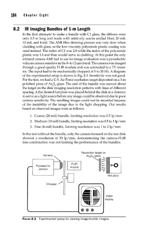
tor. The input had to be mechanically chopped at 5 to 20 Hz. A diagram
of the experimental setup is shown in Fig. 8.3. Sensitivity was not good.
For the test, we had a U.S. Air Force resolution target deposited on a 3-in
polished piece of As S glass. The end of the bundle was moved about
2 3
the target on the disk imaging resolution patterns with lines of different
spacing. A flat, heated hot plate was placed behind the disk at a distance
to serve as a light source before any image could be observed due to poor
camera sensitivity. The resulting images could not be recorded because
of the instability of the image due to the light chopping. Our results
based on observed images were as follows:
1. Coarse (20-mil) bundle, limiting resolution was 0.5 lp/mm
2. Medium (10-mil) bundle, limiting resolution was 0.5 to 1 lp/mm
3. Fine (4-mil) bundle, limiting resolution was 1 to 2 lp/mm
In the test without the bundle, only the camera focused on the test disk
showed a resolution of 30 lp/mm, demonstrating the camera-FLIR
lens combination was not limiting the performance of the bundles.
Resolution target on
Ge lens As 2 S 3 glass
FLIR
Pyroelectric module
camera
Hot plate
Chopper
0
1
2 Video
3 012345
4 display
5
FIGURE 8.3 Experimental setup for viewing image-bundle images.