
Page 228 - Chalcogenide Glasses for Infrared Optics
P. 228
204 Cha pte r Ei g h t
section where the ribbons could be formed and the layers could be
fused. At the end, the fused area would be cut in the middle to pro-
vide the coherent ends. The bodies of the fibers were wound on a thin
sheet of plastic stuck to the drum. When the winding was complete,
the edges of the plastic were folded over the loose fibers and sealed to
form a thin plastic sack the entire length of the bundle. After the fused
area was cut in the middle, the thin sack was placed in a shrinkable
plastic tube, heated to size, and sealed on each end to the metal con-
nectors. The bundle was wound from very high purity glass, all from
the same plate, homogeneous, striae-free, and low in water absorp-
tion (< 1 dB/m) and in hydrogen sulfide absorption (< 5 dB/m). The
quality of the glass led to a failure-free winding process with four
cores from the plate completing the bundle. The ribbon count was
66 unclad fibers, core diameter 108 µm, 47 layers for a total of 31,020 m.
The calculated active area was 71.2 percent, our record (absolute
maximum is 78.5 percent). The extra bundle was fabricated to employ
all we had learned to prepare a final improved version.
8.4.6 Optical Evaluation of 10-m Imaging Bundles
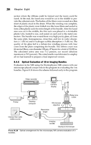
Evaluation in the NIR using the Electrophysics NIR camera with our
microscope played a major role in the program in evaluating the 1-m
bundles. Figure 8.18 shows the scheme followed early in the program
Video recorder
12:00
12:00
Camera
Video
display
Relay lens
0.55X
Printer Desktop
computer Microscope
objective
Resolution
target
Intense fiber-optic
visible source
Imaging
bundle
Olympus microscope
FIGURE 8.18 Optical arrangement for the microscope/NIR camera evaluation of ir
bundles.