
Page 226 - Chalcogenide Glasses for Infrared Optics
P. 226
202 Cha pte r Ei g h t
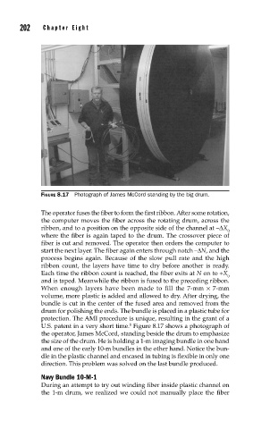
FIGURE 8.17 Photograph of James McCord standing by the big drum.
The operator fuses the fiber to form the first ribbon. After some rotation,
the computer moves the fiber across the rotating drum, across the
ribbon, and to a position on the opposite side of the channel at –∆X
0
where the fiber is again taped to the drum. The crossover piece of
fiber is cut and removed. The operator then orders the computer to
start the next layer. The fiber again enters through notch –∆N, and the
process begins again. Because of the slow pull rate and the high
ribbon count, the layers have time to dry before another is ready.
Each time the ribbon count is reached, the fiber exits at N on to +X
0
and is taped. Meanwhile the ribbon is fused to the preceding ribbon.
When enough layers have been made to fill the 7-mm × 7-mm
volume, more plastic is added and allowed to dry. After drying, the
bundle is cut in the center of the fused area and removed from the
drum for polishing the ends. The bundle is placed in a plastic tube for
protection. The AMI procedure is unique, resulting in the grant of a
8
U.S. patent in a very short time. Figure 8.17 shows a photograph of
the operator, James McCord, standing beside the drum to emphasize
the size of the drum. He is holding a 1-m imaging bundle in one hand
and one of the early 10-m bundles in the other hand. Notice the bun-
dle in the plastic channel and encased in tubing is flexible in only one
direction. This problem was solved on the last bundle produced.
Navy Bundle 10-M-1
During an attempt to try out winding fiber inside plastic channel on
the 1-m drum, we realized we could not manually place the fiber