
Page 221 - Chalcogenide Glasses for Infrared Optics
P. 221
IR Imaging Bundles Made fr om Chalcogenide Glass Fibers 197
PERKIN ELMER
5000 4000 3500 3000 2500 2000 1500 1000 cm –4
100.00
%T
Hcursor 10.00 5.0000; 18.39% T Uncoated reflection
3.0000; 2.43% T 4.0000; 2.47% T 3% reflectivity
0.00
2.000 3.000 4.000 5.000 6.000 7.000 8.000 9.000 10.000 11.000 12.000 13.000 14.000
Wavelength (µm)
99/04/26 11:10
X: 10 scans, 4.0 cm –1
99-f2 as2s3 wedge vs SI backg.
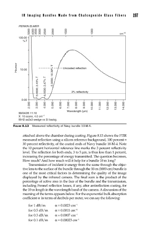
FIGURE 8.13 Measured refl ectivity of Navy bundle 10-M-4.
attached above the chamber during coating. Figure 8.13 shows the FTIR
measured reflection using a silicon reference background, 100 percent =
30 percent reflectivity, of the coated ends of Navy bundle 10-M-4. Note
the 10 percent horizontal reference line marks the 3 percent reflectivity
level. The reflection for both ends, 3 to 5 µm, is thus less than 1 percent,
increasing the percentage of energy transmitted. The question becomes,
How much? And how much will it help for a bundle 10 m long?
Transmission of incident ir energy from the scene through the objec-
tive lens to the surface of the bundle through the 10-m (1000-cm) bundle is
one of the most critical factors in determining the quality of the image
displayed by the infrared camera. The final sum is the product of the
percentage of active area in the face of the bundle and the transmission,
including Fresnel reflection losses, if any, after antireflection coating, for
the 10-m length in the wavelength band of the camera. A discussion of the
meaning of the terms appears below. For the exponential bulk absorption
coefficient α in terms of decibels per meter, we can say the following:
for 1 dB/m α= 0.0023 cm −1
for 0.5 dB/m α= 0.0011 cm −1
for 0.3 dB/m α= 0.0007 cm −1
for 0.1 dB/m α= 0.00023 cm −1