
Page 223 - Chalcogenide Glasses for Infrared Optics
P. 223
IR Imaging Bundles Made fr om Chalcogenide Glass Fibers 199
5000 4500 4000 3500 3000 2500 2000 cm –4
100.00
%T
2.2605; 87.77% T 2.4387; 90.31% T 2.7106; 89.71% T 4.8632; 82.74% T 0.2 dB/m
80 0.1 dB/m
% Transmission 60 5.3262; 58.85% T 0.3 dB/m
0.4 dB/m
40
2.8951; 2.40% T 3.3106; 31.71% T 1.0 dB/m
20 3.0995; 9.77% T 3.8326; 41.07% T 5.1547; 45.94% T 5.5657; 36.81% T 5.7232; 43.02% T 0.5 dB/m
0.00
2.000 2.500 3.000 3.500 4.000 4.500 5.000 5.500 6.000
10-m length
99/02/17 10:18 Θ CO laser transmission @ 5.25 µm
X: 10 scans, 4.0 cm –1
11 vs 1 m .020 C–2 Fiber S–99–1–3
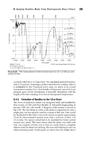
FIGURE 8.14 FTIR measurement of internal transmission for 10 m of 500-µm core
unclad C2 fi ber.
counted within the 3- to 5-µm band. The calculated internal transmis-
sion is 37 percent. Assuming a perfect antireflection coating, when it
is multiplied by the 70 percent active area, we arrive at an overall
transmission number for a 10-m bundle of 26 percent, one-half of our
program goal. Severe broadening of impurity absorption with the
length of the fiber reaching 10 m was an unexpected complication.
8.4.5 Formation of Bundles on the 10-m Drum
The 10-m-circumference drum was designed, built, and installed by
Tom Loretz of CES and Paul Modlin of Advantek Engineering in
January 1999, the 11th month. A diagram of the system is shown in
Fig. 8.15. The first thing to notice is the drum is supported by only a
single post, not two usually used for a drum of this size. One would
be insufficient if the fibers were to be drawn at speeds approaching
70 mi/h. Our intended speeds were only a fraction of that, 5 to
10 m/min. The speed control had to be modified for better control
around zero speed. The main reason that the drum was built with
only one support column was so that we could remove complete
ribbons from the drum for stacking. We were still thinking in our 1-m
ribbon stacking mode. At this point we had to face the reality that it