
Page 261 - Chalcogenide Glasses for Infrared Optics
P. 261
236 Cha pte r Ni ne
9
10 6 10 7 10 8 10 10 10 10 11 10 12 10 13 10 14 10 15 10 16 10 17 10 18 10 19
10 9 10 9
10 8 10 8
10 7 10 7
10 6 5 10 6 5
Resistivity (Ω·cm) (log) 10 4 3 2 10 4 3 2 Resistivity (Ω · cm) (log)
10
10
10
10
10
10
10
1
1 10
10 –1 10 –1
10 –2 10 –2
10 –3 10 –3
10 –4 10 –4
9
10 6 10 7 10 8 10 10 10 10 11 10 12 10 13 10 14 10 15 10 16 10 17 10 18 10 19
3
Carrier concentration/cm (log)
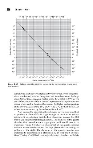
FIGURE 9.17 Gallium arsenide resistivity versus carrier concentration N-type room
temperature.
centimeters. Not only was signal lost by absorption when the germa-
nium was heated, but also the system lost focus because of the large
index ∆N/∆T for germanium heated above 25°C of 450 × 10 /°C. The
−6
use of GaAs in place of Ge in the tank system would improve perfor-
mance when used in the desert because of the higher use temperature
−6
and a lower ∆N/∆T above 25°C of 207 × 10 /°C. Both of the ∆N/∆T
values were measured by the author while still at TI.
AMI decided to direct its efforts toward developing a method
to produce a plate of GaAs large enough to serve as an avionic
window. It was obvious that the best chance for success for AMI
was to use its horizontal Bridgman unit. The diameter of the quartz
chamber that housed a much larger plate mold would have to be
increased. Figure 9.18 shows a photograph of the quartz chamber
with the arsenic on the left and the large plate mold containing the
gallium on the right. The diameter of the quartz chamber was
increased to accommodate a plate mold 12 in long and 6 in wide.
Glen Whaley of AMI had routinely fabricated chambers with 8-in