
Page 369 - Challenges in Corrosion Costs Causes Consequences and Control(2015)
P. 369
CORROSION DAMAGE, DEFECTS, AND FAILURES 347
Flame or arc-spray
Primary anode zinc anode
Steel rebar
Electrical i
bond
Reinforced concrete
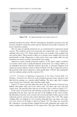
Figure 5.25 Arc-sprayed galvanic layer anode system (19).
potential should be less than −200 mV, indicating the breakdown of passive film; the
structure should be sound; the reinforcing bars should be electrically continuous; AC
power should be available.
The two types of cathodic protection are: (i) sacrificial and (ii) impressed current
systems. The sacrificial anode system typically uses magnesium, zinc, or aluminum
and their alloys (Fig. 5.25). These metals or alloys act as anodes when coupled with
steel and its alloys. These metals or alloys act as anodes when coupled with steel and
preferentially corrode. Magnesium is often used in fresh water media while zinc and
aluminum are used in seawater and brackish water media.
Impressed current cathodic protection requires: (i) DC power supply (rectifier);
(ii) an inert anode such as catalyzed titanium anode mesh; (iii) wiring conduit; (iv)
an embedded silver/silver chloride reference electrode. A schematic diagram of an
impressed current cathodic system is shown in Figure 5.26. By an impressed current,
the potential of the steel is adjusted to values greater than −850 mV, thus making the
steel bar cathodic and prevent the corrosion (25).
5.3.7.4.8 Corrosion of Aluminum Components in the Glass Curtain Wall of a
Building Corrosion was observed on the aluminum pressure plates and dress caps
that hold the glazing on a curtain-walled building. The dress caps with L-shaped
cross sections were externally clad with thin copper sheet.
Figure 5.27 shows a pressure plate and a dress cap. The aluminum extrusions were
hidden with rubber strips and screws (dress caps). The dress caps were clad with
copper sheet. The pressure plate with one of the dress caps is shown in Figure 5.27.
In the course of several years after building construction, the copper cladding was
separating from the dress caps near the base of the building. In the course of time,
the aluminum extrusions were covered with corrosion products (white–gray in color)
indicating general corrosion and a pitted aluminum surface (Fig. 5.28). The copper
cladding sheet was bulged at a few locations along the dress cap edges, and a typ-
ical cross section of the bulge is shown in Figure 5.29. The bulge was caused by
the voluminous corrosion product trapped between the aluminum and copper ulti-
mately leading to the deformation of soft copper sheet. The figure shows aluminum