
Page 374 - Challenges in Corrosion Costs Causes Consequences and Control(2015)
P. 374
352 CONSEQUENCES OF CORROSION
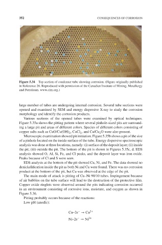
Figure 5.34 Top section of condenser tube showing corrosion. (Figure originally published
in Reference 26. Reproduced with permission of the Canadian Institute of Mining, Metallurgy
and Petroleum. www.cim.org.)
large number of tubes are undergoing internal corrosion. Several tube sections were
opened and examined by SEM and energy dispersive X-ray to study the corrosion
morphology and identify the corrosion products.
Various sections of the opened tubes were examined by optical techniques.
Figure 5.35a shows the pitting pattern where several pinhole-sized pits are surround-
ing a large pit and areas of different colors. Species of different colors consisting of
copper salts such as CuO/Cu(OH) ,CuCl , and Cu/Cu O were also present.
2 2 2
Microscopic examination showed pit initiation. Figure 5.35b shows a pit of the size
of a pinhole located on the inside surface of the tube. Energy dispersive spectroscopic
analysis was done at three locations, namely: (i) surface of the deposit layer; (ii) inside
the pit; (iii) outside the pit. The bottom of the pit is shown in Figures 5.35c, d. EDS
analysis showed O, Al, Si, Fe, and Cl peaks, and the deposit layer was iron oxide.
Peaks because of Cl and S were seen.
EDS analysis at the bottom of the pit showed Cu, Ni, and Fe. The data showed no
denickelification inside the pit as both Ni and Cu were found. There was no corrosion
product at the bottom of the pit, but Cu was observed at the edge of the pit.
The main mode of attack is pitting of Cu–Ni 90/10 tubes. Impingement because
of air bubbles on the tube surface will lead to the destruction of the protective film.
Copper oxide ringlets were observed around the pits indicating corrosion occurred
in an environment consisting of corrosive ions, moisture, and oxygen as shown in
Figure 5.36.
Pitting probably occurs because of the reactions:
Low pH (anodic):
− 2+
Cu–2e → Cu
−
Ni–2e → Ni 2+