
Page 378 - Challenges in Corrosion Costs Causes Consequences and Control(2015)
P. 378
356 CONSEQUENCES OF CORROSION
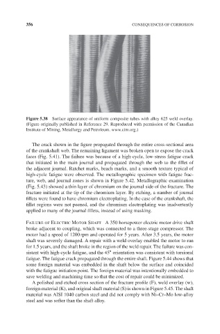
Figure 5.38 Surface appearance of uniform composite tubes with alloy 625 weld overlay.
(Figure originally published in Reference 29. Reproduced with permission of the Canadian
Institute of Mining, Metallurgy and Petroleum. www.cim.org.)
The crack shown in the figure propagated through the entire cross-sectional area
of the crankshaft web. The remaining ligament was broken open to expose the crack
faces (Fig. 5.41). The failure was because of a high-cycle, low-stress fatigue crack
that initiated in the main journal and propagated through the web to the fillet of
the adjacent journal. Ratchet marks, beach marks, and a smooth texture typical of
high-cycle fatigue were observed. The metallographic specimen with fatigue frac-
ture, web, and journal zones is shown in Figure 5.42. Metallographic examination
(Fig. 5.43) showed a thin layer of chromium on the journal side of the fracture. The
fracture initiated at the tip of the chromium layer. By etching, a number of journal
fillets were found to have chromium electroplating. In the case of the crankshaft, the
fillet regions were not peened, and the chromium electroplating was inadvertently
applied to many of the journal fillets, instead of using masking.
Failure of Electric Motor Shaft A 350 horsepower electric motor drive shaft
broke adjacent to coupling, which was connected to a three-stage compressor. The
motor had a speed of 1200 rpm and operated for 5 years. After 3.5 years, the motor
shaft was severely damaged. A repair with a weld overlay enabled the motor to run
for 1.5 years, and the shaft broke in the region of the weld repair. The failure was con-
∘
sistent with high-cycle fatigue, and the 45 orientation was consistent with torsional
fatigue. The fatigue crack propagated through the entire shaft. Figure 5.44 shows that
some foreign material was embedded in the shaft below the surface and coincided
with the fatigue initiation point. The foreign material was intentionally embedded to
save welding and machining time so that the cost of repair could be minimized.
A polished and etched cross section of the fracture profile (F), weld overlay (w),
foreign material (K), and original shaft material (S) is shown in Figure 5.45. The shaft
material was AISI 1040 carbon steel and did not comply with Ni–Cr–Mo low-alloy
steel and was softer than the shaft alloy.