
Page 380 - Challenges in Corrosion Costs Causes Consequences and Control(2015)
P. 380
358 CONSEQUENCES OF CORROSION
Figure 5.40 Appearance of large crankshaft crack. (Figure originally published in Refer-
ence 26. Reproduced with permission of the Canadian Institute of Mining, Metallurgy and
Petroleum. www.cim.org.)
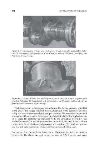
Figure 5.41 Fatigue fracture face showing crack growth direction. (Figure originally pub-
lished in Reference 26. Reproduced with permission of the Canadian Institute of Mining,
Metallurgy and Petroleum. www.cim.org.)
The failure appears to be torsional fatigue failure. The foreign substance embedded
in the area of the fatigue initiation point is suggestive of the subsurface anomaly
acting as a stress raiser responsible for fatigue initiation. The amount of fatigue crack
propagation did not result in breaking of the shaft indicative of low applied stresses
on the shaft. The problem was intensified by the low strength of the weld overlay
material because of its low fatigue resistance. In addition, the shaft material did not
comply with the required material properties and standards. The shaft strength was
also low and had a detrimental effect on the fatigue strength of the shaft.
Failure of Pipe Clamp Joint Connector The clamp that failed is shown in
Figure 5.46. The clamp was used to join two ends of NPS 8 carbon steel steam