
Page 381 - Challenges in Corrosion Costs Causes Consequences and Control(2015)
P. 381
CORROSION DAMAGE, DEFECTS, AND FAILURES 359
W F
J
CM 1 2
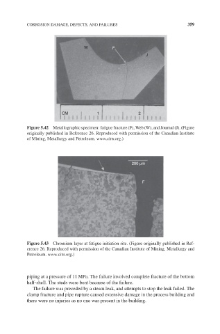
Figure 5.42 Metallographic specimen: fatigue fracture (F), Web (W), and Journal (J). (Figure
originally published in Reference 26. Reproduced with permission of the Canadian Institute
of Mining, Metallurgy and Petroleum. www.cim.org.)
200 μm
F
Figure 5.43 Chromium layer at fatigue initiation site. (Figure originally published in Ref-
erence 26. Reproduced with permission of the Canadian Institute of Mining, Metallurgy and
Petroleum. www.cim.org.)
piping at a pressure of 11 MPa. The failure involved complete fracture of the bottom
half-shell. The studs were bent because of the failure.
The failure was preceded by a steam leak, and attempts to stop the leak failed. The
clamp fracture and pipe rupture caused extensive damage in the process building and
there were no injuries as no one was present in the building.