
Page 382 - Challenges in Corrosion Costs Causes Consequences and Control(2015)
P. 382
360 CONSEQUENCES OF CORROSION
K
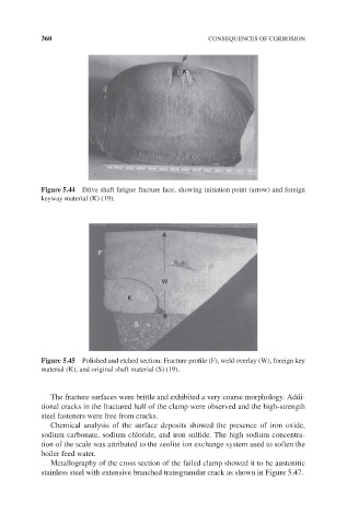
Figure 5.44 Drive shaft fatigue fracture face, showing initiation point (arrow) and foreign
keyway material (K) (19).
F
W
K
S
Figure 5.45 Polished and etched section: Fracture profile (F), weld overlay (W), foreign key
material (K), and original shaft material (S) (19).
The fracture surfaces were brittle and exhibited a very coarse morphology. Addi-
tional cracks in the fractured half of the clamp were observed and the high-strength
steel fasteners were free from cracks.
Chemical analysis of the surface deposits showed the presence of iron oxide,
sodium carbonate, sodium chloride, and iron sulfide. The high sodium concentra-
tion of the scale was attributed to the zeolite ion exchange system used to soften the
boiler feed water.
Metallography of the cross section of the failed clamp showed it to be austenitic
stainless steel with extensive branched transgranular crack as shown in Figure 5.47.