
Page 391 - Challenges in Corrosion Costs Causes Consequences and Control(2015)
P. 391
CORROSION DAMAGE, DEFECTS, AND FAILURES 369
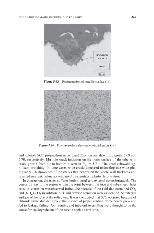
Corrosion
products
Metal
90 μm
Figure 5.63 Fragmentation of metallic surface (19).
90 μm
Figure 5.64 Fracture surface showing equiaxial grains (19).
and chloride SCC propagation in the axial direction are shown in Figures 5.69 and
5.70, respectively. Multiple crack initiation on the outer surface of the tube with
crack growth from top to bottom is seen in Figure 5.71a. The cracks showed sig-
nificant branching. In some cases, wide cracks appeared to develop into wide pits.
Figure 5.71b shows one of the cracks that penetrated the whole wall thickness and
resulted in a leak failure accompanied by significant plastic deformation.
In conclusion, the tubes suffered both internal and external corrosion attack. The
corrosion was in the region within the joint between the tube and tube sheet. Inlet
erosion–corrosion was observed in the tube because of the fluid that contained CO 2
and (NH ) CO in solution. SCC and crevice corrosion were evident on the external
4 2
3
surface of the tube at the rolled end. It was concluded that SCC occurred because of
chloride in the shielded area in the absence of proper venting. Some cracks grew and
led to leakage failure. Poor venting and tube-end overrolling were thought to be the
cause for the degradation of the tube in such a short time.