
Page 393 - Challenges in Corrosion Costs Causes Consequences and Control(2015)
P. 393
CORROSION DAMAGE, DEFECTS, AND FAILURES 371
Seal weld
316L stainless steel tube
Rolled joint
~100 mm
Tubesheet
Condensate Vapor phase
(Dead space)
Vapor
Cooling water
Process fluid
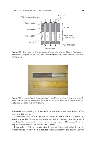
Figure 5.67 Top portion of HPS condenser. (Figure originally published in Reference 26.
Reproduced with permission of the Canadian Institute of Mining, Metallurgy and Petroleum.
www.cim.org.)
Figure 5.68 Inner surface of the tube covered by black/brown oxide. (Figure originally pub-
lished in Reference 26. Reproduced with permission of the Canadian Institute of Mining,
Metallurgy and Petroleum. www.cim.org.)
depression. Macroetching with 50% HCl for 30 s enabled the identification of the
fracture initiation site.
A transverse cross section through the fracture initiation site was examined by
metallography. The fracture surface profile was relatively flat and there was no crack
branching. The microstructure showed dark-etching-tempered Martensite. There was
no plastic deformation at the fracture initiation site.
It is concluded (28) that the pin failed because of fatigue initiated at the outside
cylindrical surface where wear and pitting corrosion occurred. The fracture initiated