
Page 137 - Chemical Process Equipment - Selection and Design
P. 137
6.7. GASES 109
1.00
L
- 0.10
0 -
L
0
0
LL u
0 -
c
9
w I; 0.01
-.-_- ExtraDolated Regions
-- ExDerimznta Regions
0.001
1,000 1.000 loo,( 100
REYNOLDS NUMBER, Re,,
(a)
Figure 6.5. Fri~ct/on factors in laminar and turbulent flows of power-law and Bingham liquids. (a For pseudoplastic liquids represented by
-
z, = K'(8V/DIn , %with K' and n' constant or dependent on T,: l/$= [4.0/(n')0~75~~og10[Re,,f(')-"'2~] 0.40/(nf)'.', [Dodge and Metzner,
AIChE 9. 5, 289 (1959)l. (b) For Bingham plastics, Re, = DVp/p,, He = z,Dzp/p, [Hanks and Dadia, AIChE J. 17, 554 (2971)l.
evaluating K' and PI' in the range of sheas stress tW = DAP/4L that
will prevail in the required situation.
Bingham flow is represented by Figure 6.5(b) in terms of
Reynolds and IHedstrom numbers.
Theoretical relations for generalized Bingham flow [Eq. (6.47)]
have been devised by Torrance [S. Afr. 1Mech. Eng. W, 89 (1963)].
They are
1 l2.69
3=K-
1.97 0.68
+ -- ln(Re;f1-"'2) + ~ (5n - 8) (6.59)
n
lo3 lo4 105 106 IO'
HEOSTROM NUMBER (NHel
with the Reynolds number
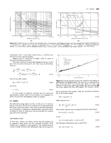
Figure 6.6, Critical Reynolds number for transition from laminar to
Re, = D"V2-"p/8"-1K (6.60) turbulent flow of Bingham fluids. The data also are represented by
Eqs. (6.56) and (6.57): (0) cement rock slurry; (A) river mud
and where slurries; (0) clay slurry; (0) sewage sludge; (A) Tho, slurries; (U)
lime slurry. [Hanks and Pratt, SPE Journal, 342-346 (Dec. 2967)].
x = zo/zw. (6.61)
power production with turbines. With the assumptions indicated,
In some ranges of operation, materials may be represented Eq. (6.10) becomes simply
approximately equally well by several models, as in Example 6.11
where the power-law and Bingham models are applied. dH + (l/g,)u du = 0, (6.62)
which integrates into
6.7. GASES
The differential energy balances of Eqs. (6.10) and (6.15) with the H, - HI + - (u; - uf) i= 0. (6.63)
1
friction term of Eq. (6.18) can be integrated for compressible fluid 2gc
flow under certain restrictions. Three cases of particular importance
are of isentropic or isothermal or adiabatic flows. Equations will be One of these velocities may be eliminated with the mass balance,
developed for them for ideal gases, and the procedure for nonideal
gases also will be indicated. m = u2A2/V2 = u1A,/V1 (6.64)
so that
ISENTROPIC FLOW
u$ - u: = (ritV,/A,)2[1 - (A,Vl/AlVz)2]. (6.65)
In short lines., nozzles, and orifices, friction and heat transfer may
be neglected, which makes the flow essentially isentropic. Work For ideal gases substitutions may be made from
transfer also is negligible in such equipment. The resulting theory is
a basis 0f design of nozzles that will generate high velocity gases for