
Page 230 - Chemical Process Equipment - Selection and Design
P. 230
200 HEAT TRANSFER AND HEAT EXCHANGERS
some arbitrary decisions based on as much current practice as
WAR END
fl in Figure 8.13. The key elements are:
possible.
MUD NPLI
A logic diagram of a heat exchanger design procedure appears
<:--Tj>
FIXED TUBESHEET
ONE
PASS
-I . ..................... WELL LIKE "A" STATIONARY HEAD 1. Selection of a tentative set of design parameters, Box 3 of Figure
8.13(a).
2. Rating of the tentative design, Figure 8.13(b), which means
FIXED TUBESHEET
TWO PAS SHELL LIKE "0" STATIONARY HE4D evaluating the performance with the best correlations and
wim LONGITUDINAL BAFFLE
calculation methods that are feasible.
3. Modification of some design parameters, Figure 8.13(c), then
rerating the design to meet thermal and hydraulic specifications
FIXED TUBESHEET
I LlKE 'W STATIONARY HEAD and economic requirements.
SPLIT FLOW
A procedure for a tentative selection of exchanger will be
.
.
. . _.._ .-.
IUTSIDE PACKED FLOATING HEA described following. With the exercise of some judgement, it is
feasible to perform simpler exchanger ratings by hand, but the
DOUBLE SPLll FLOW
present state of the art utilizes computer rating, with in-house
programs, or those of HTRI or HTFS, or those of commercial
services. More than 50 detailed numerical by hand rating examples
are in the book of Kern (1950) and several comprehensive ones in
the book of Ganapathy (1982).
PULL THROUGH FLOATING HEAI
TENTATIVE DESIGN
KEinE TYPE REBOILEP I The stepwise procedure includes statements of some rules based on
common practice.
U-TUBE BUNDLE
c:r-7;,
1. Specify the flow rates, terminal temperatures and physical
1 properties.
EXTERNALLY SEALED
SPECIAL HIGH PRESIURL CLOSUIII CROSS FLOW PLOAIING TUBESHEEl 2. Calculate the LMTD and the temperature correction factor F
from Table 8.3 or Figure 8.5.
(a) 3. Choose the simplest combination of shell and tube passes or
number of shells in series that will have a value of F above 0.8 or
so. The basic shell is 1-2, one shell pass and two tube passes.
4. Make an estimate of the overall heat transfer coefficient from
Tables 8.4-8.7.
5. Choose a tube length, normally 8, 12, 16, or 20 ft. The 8 ft long
exchanger costs about 1.4 times as much as the 20 ft one per unit
of surface.
4
6. Standard exchanger tube diameters are 0.75 or lin. OD, with
pitches shown in Table 8.13.
7. Find a shell diameter from Table 8.13 corresponding to the
selections of tube diameter, length, pitch, and number of passes
made thus far for the required surface. As a guide, many heat
exchangers have length to shell diameter ratios between 6 and 8.
8. Select the kinds and number of baffles on the shell side.
The tentative exchanger design now is ready for detailed
evaluation with the best feasible heat transfer and pressure drop
data. The results of such a rating will suggest what changes may be
needed to satisfy the thermal, hydraulic, and economic require-
ments for the equipment. Example 8.10 goes through the main part
1. SHELL 8. FLOATING HEAD FWGE 16. TRANSVERSE BAFFLES OR of such a design.
2. SHELL COVER 9. CHANNEL PARTITION SUPPORT PLATES
3. SHELLCHWNEL 10. STATIONARY TUBESHEET 18. IMPINGEMENT BAFFLE
1. 5HELLCOVEfl END FLANGE 11. CHANNEL 17. VENT CONNECTION
6. SHELLNOZZLE 12. CHANNELCOVER 18. DRAIN CONNECTION 8.8. CONDENSERS
6, f LOATING TUBESHEET 13. CHANNEL NOZZLE 19. TEST CONNECTION
1. FLOATING HEAD 14. TIE ROD9 ANDSPACERS 20. SUPPORT SADDLES
21. LlFTlNGRlNG Condensation may be performed inside or outside tubes, in
horizontal or vertical positions. In addition to the statements made
in the previous section about the merits of tube side or shell side:
When freezing can occur, shell side is preferable because it is less
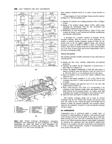
Figure 8.11. Tubular Exchanger Manufacturers Association likely to clog. When condensing mixtures whose lighter components
classification and terminology for heat exchangers. (a) TEMA are soluble in the condensate, tube side should be adopted since
terminology for shells and heads of heat exchangers. (b) drainage is less complete and allows condensation (and dissolution)
Terminology for parts of a TEMA type AES heat exchanger. The to occur at higher temperatures. Venting of noncondensables is
three letters A, E, and S come from part (a). more positive from tube side.