
Page 235 - Chemical Process Equipment - Selection and Design
P. 235
8.8. CONDENSERS 205
R Vapor
Tubesheet vent 1
Water ' out
Water out Special water
' bafile
I
Vent 1
date
Water in
Funnel Packed head Packed head
separator
Slip-on flange
with split ring r,
Slip-on flange
with split ring
-
Baffle plate
Eeparator Water distributor
designs
I
Water out )rain hole
Alternate head Condensate
Condensat
(a) (b)
Water out Vapor Vapor vent
1
I I I
Water in Baffle rotated 90" Condensate Split ring head
(d)
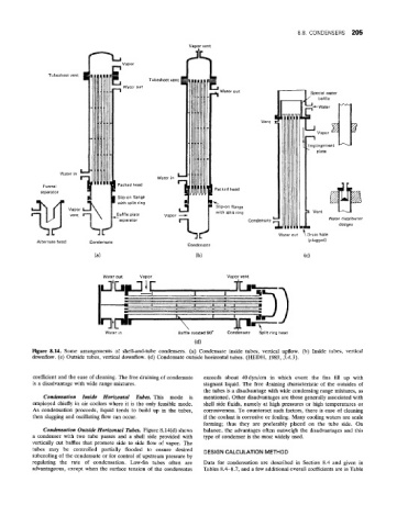
Figme 8.14. Some ar ,rangements of shell-and-tube condensers. (a) Condensate inside tubes, vertical upflow. (b) Inside tubes, vertical
downfl ow. (c) Outside tubes, vertical downflow. (d) Condensate outside horizontal tubes. (HEDH, 1983, 3.4.3).
coefficient and the ease of cleaning. The free draining of condensate exceeds about 40dyn/cm in which event the fins fill up with
is a disadvantage with wide range mixtures. stagnant liquid. The free draining characteristic of the outsides of
the tubes is a disadvantage with wide condensing range mixtures, as
Condensation Inside Horizontal Tubes. This mode is mentioned. Other disadvantages are those generally associated with
employed chiefly in air coolers where it is the only feasible mode. shell side fluids, namely at high pressures or high temperatures or
As condensation proceeds, liquid tends to build up in the tubes, corrosiveness. To counteract such factors, there is ease of cleaning
then slugging and oscillating flow can occur. if the coolant is corrosive or fouling. Many cooling waters are scale
forming; thus they are preferably placed on the tube side. On
Condensation Outside Horizontal Tubes. Figure 8.14(d) shows balance, the advantages often outweigh the disadvantages and this
a condenser with two tube passes and a shell side provided with type of condenser is the most widely used.
vertically cut baffles that promote side to side flow of vapor. The
tubes may be controlled partially flooded to ensure desired DESIGN CALCULATION METHOD
subcooling of the condensate or for control of upstream pressure by
regulating the rate of condensation. Low-fin tubes often are Data for condensation are described in Section 8.4 and given in
advantageous, except when the surface tension of the condensates Tables 8.4-8.7, and a few additional overall coefficients are in Table