
Page 236 - Chemical Process Equipment - Selection and Design
P. 236
206 HEAT TRANSFER AND HEAT EXCHANGERS
7. Continue with other specifications of the vapor temperature T,,
one interval at a time, until the required outlet temperature is
reached.
m I Coolant phase 8. The heat transfer area will be found by numerical integration of
Gas phase
(8.39)
TL
Examples of numerical applications of this method are in the
original paper of Colburn and Hougen (1934), in the book of Kern
(1950, p. 346) and in the book of Ludwig (1983, Vol. 3, p. 116).
Interlace - The Silver-Bell-Ghaly Method
PI 8 T, This method takes advantage of the rough proportionality between
heat and mass transfer coefficients according to the Chilton-
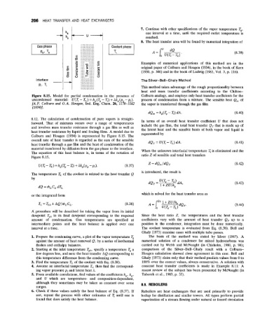
Figure 8.15. Model for partial condensation in the presence of Colburn analogy, and employs only heat transfer coefficients for the
uncondensed material: U(T - TL) = hg(Tg - T) + Akg(p, -pi). process of condensation from a mixture. The sensible heat Q, of
[A.P. Colburn and O.A. Hougen, Ind. Eng. Chem. 26, 1178-1182 the vapor is transferred through the gas film
(1 934)J
dQ, = h,(T, - Ti) dA. (8.40)
8.12. The calculation of condensation of pure vapors is straight- In terms of an overall heat transfer coefficient U that does not
forward. That of mixtures occurs over a range of temperatures include the gas film, the total heat transfer QT that is made up of
and involves mass transfer resistance through a gas film as well as the latent heat and the sensible heats of both vapor and liquid is
heat transfer resistance by liquid and fouling films. A model due to represented by
Colburn and Hougen (1934) is represented by Figure 8.15. The
overall rate of heat transfer is regarded as the sum of the sensible dQT = U(q - TL) dA. (8.41)
heat transfer through a gas film and the heat of condensation of the
material transferred by diffusion from the gas phase to the interface. When the unknown interfacial temperature is eliminated and the
The equation of this heat balance is, in terms of the notation of ratio Z of sensible and total heat transfers
Figure 8.15,
u(T - TL) = hg(Tg - I;) + akg(pg -pi). (8.37)
is introduced, the result is
The temperature TL of the coolant is related to the heat transfer Q
by
(8.43)
dQ = mLCL dT,
or the integrated form which is solved for the heat transfer area as
TL = TLo + AQlmLCL. (8.38) (8.44)
A procedure will be described for taking the vapor from its initial
dewpoint Tgo to its final dewpoint corresponding to the required Since the heat ratio Z, the temperatures and the heat transfer
amount of condensation. Gas temperatures are specified at coefficients vary with the amount of heat transfer QT up to a
intermediate points and the heat balance is applied over one position in the condenser, integration must be done numerically.
interval at a time. The coolant temperature is evaluated from Eq. (8.38). Bell and
Ghaly (1973) examine cases with multiple tube passes.
1. Prepare the condensing curve, a plot of the vapor temperature T, The basis of the method was stated by Silver (1947). A
against the amount of heat removed Q, by a series of isothermal numerical solution of a condenser for mixed hydrocarbons was
flashes and enthalpy balances. carried out by Webb and McNaught (in Chisholm, 1980, p. 98);
2. Starting at the inlet temperature Tgo, specify a temperature T, a comparison of the Silver-Bell-Ghaly result with a Colburn-
few degrees less, and note the heat transfer AQ corresponding to Hougen calculation showed close agreement in this case. Bell and
this temperature difference from the condensing curve. Ghaly (1973) claim only that their method predicts values from 0 to
3. Find the temperature TL of the coolant with Eq. (8.38). 100% over the correct values, always conservative. A solution with
4. Assume an interfacial temperature T, then find the correspond- constant heat transfer coefficients is made in Example 8.11: A
ing vapor pressure pi and latent heat A. recent review of the subject has been presented by McNaught (in
5. From available correlations, find values of the coefficients h,, k,, Taborek et al., 1983, p. 35).
and U which are temperature- and composition-dependent,
although they sometimes may be taken as constant over some
ranges. 8.9. REBOILERS
6. Check if these values satisfy the heat balance of Eq. (8.37). If Reboilers are heat exchangers that are used primarily to provide
not, repeat the process with other estimates of I;. until one is boilup for distillation and similar towers. All types perform partial
found that does satisfy the heat balance. vaporization of a stream flowing under natural or forced circulation