
Page 234 - Chemical Process Equipment - Selection and Design
P. 234
204 HEAT TRANSFER AND HEAT EXCHANGERS
EXAMPLE 8.10 Use 16 ft tubes on li in. square pitch, two pass, 33 in. shell
Process Design of a Shell-and-Tube Heat Exchanger
An oil at the rate of 490,000 lb/hr is to be heated from 100 to 170°F LID = 16/(33/12) = 5.82,
with 145,000 lb/hr of kerosene initially at 390°F. Physical properties
are
which is near standard practice. The 20 ft length also is acceptable
but will not be taken.
Oil 0.85 sp gr, 3.5 CP at 135"F, 0.49 sp ht
Kerosene 0.82 sp gr, 0.4 CP at 200"F, 0.61 sp ht The pressure drops on the tube and shell sides are to be
calculated.
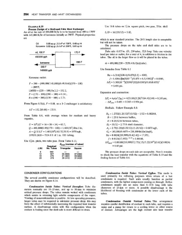
oil, 100 F Tube side: 0.875in. ID, 230 tubes, 32ft long: Take one velocity
head per inlet or outlet, for a total of 4, in addition to friction in the
tubes. The oil is the larger flow so it will be placed in the tubes.
kerosene riz = 490,000/230 = 2130.41b/(hr)(tube).
200 F
145000 pph Use formulas from Table 6.1
Re = 6.314(2130.4)/0.875(3.5) = 4392,
Kerosene outlet: f= 1.6364/[ln(5(10-7)/0.875 + 6.5/4392)]* = 0.0385,
T = 390 - (490,000/145,000)(0.49/0.61)(170 - 100) AI)= 5.385(10-8)(2130)'(32)(0.0385)/0.85(0.875)5
= 200"F, = 0.691 psi.
LMTD = (220 - 100)/ln 2.2 = 152.2, Expansion and contraction:
P (170 - 100)/(390 - 100) = 0.241,
R = (390 - 200)/(170 - 100) = 2.71. Ape = 4p(u2/2q,) = 4(53.04)(3.26)'/(64.4)(144) = 0.243 psi,
:. ACube = 0.691 + 0.243 = 0.934 psi.
From Figure 8.5(a), F = 0.88, so a 1-2 exchanger is satisfactory:
Shellside. Follow Example 8.8:
AT = 152.2(0.88) = 133.9.
Dh = 1.2732(1.25/12)'/(1/12) - 1/12 = 0.0824 ft,
From Table 8.6, with average values for medium and heavy
organics, B = 1.25 ft between baffles,
E = 0.25/12 ft between tubes,
U = 104/(57 + 16 + 50 + 34) = 63.7, D, = 33/12 = 2.75 ft shell diameter,
Q = 490,000(0.49)(170 - 100) = 1.681(107) Btu 1 hr, A, = 2.75(1.25)(0.25/12)/(1.25/12) = 0.6875 sqft,
A = Q/UAT = 1.681(10')/63.7(133.9) = 1970 sqft, G, = 145,000/0.6875 = 210,909 Ib/(hr)(sqft),
1970/0.2618 = 7524.8 ft of 1 in. OD tubing. Re = 0.0824(210,909)/0.4(2.42) = 17,952,
f= 0.0121(17,952)-0'19 = 0.00188,
Use 1: in. pitch, two tube pass. From Table 8.13, APS,,,, = 0.00l88(210,909)2(2.75)(13)/5.22(1010)(0.82)(0.0824)
Dshe,, (number of tubes)
Required = 0.85 psi.
L (ft) No. Tubes Triangular Square
8 940 - - The pressure drops on each side are acceptable. Now it remains
12 627 35 (608) 37 (584) to check the heat transfer with the equations of Table 8.10 and the
16 470 31 (462) 33 (460)
20 376 29 (410) 31 (402) fouling factors of Table 8.6.
CONDENSER CONFIGURATIONS Condensation Inside Tubes: Vertical Upflow. This mode is
used primarily €or refluxing purposes when return of a hot
The several possible condenser configurations will be described. condensate is required. Such units usually function as partial
They are shown on Figure 8.14. condensers, with the lighter components passing on through. Reflux
condensers usually are no more than 6-loft long with tube
Condensation Inside Tubes: Vertical Downfow. Tube dia- diameters of 25mm or more. A possible disadvantage is the
meters normally are 19-25mm, and up to 50mm to minimize likelihood of flooding with condensate at the lower ends of the
critical pressure drops. The tubes remain wetted with condensate tubes.
which assists in retaining light soluble components of the vapor.
Venting of noncondensables is positive. At low operating pressures,
larger tubes may be required to minimize pressure drop; this may Condensation Outside Vertical Tubes. This arrangement
have the effect of substantially increasing the required heat transfer requires careful distribution of coolant to each tube, and requires a
surface. A disadvantage exists with this configuration when the sump and a pump for return to a cooling tower or other source
coolant is fouling since the shell side is more difficult to clean. of coolant. Advantages are the high coolant side heat transfer