
Page 238 - Chemical Process Equipment - Selection and Design
P. 238
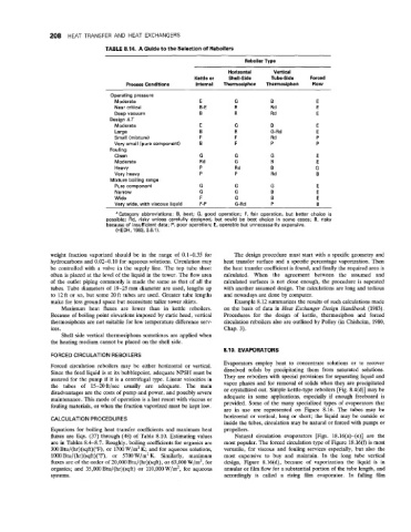
208  HEAT TRANSFER  AND  HEAT  EXCHANGERS

                                 TABLE 8.14.  A Guide to the Selection of Reboilers
                                                                          Reboiler Type
                                                                     Horizontal    Vertical
                                                           Kettle or   Shell-Side   Tube-Side   Forced
                                       Process Conditions   Internal   Therrnosiphon   Therrnosiphon   Flow
                                 ~                                                              ~
                                  Operating pressure
                                   Moderate                  E         G          B             E
                                   Near critical             B-E       R          Rd            E
                                   Deep vacuum               B         R          Rd            E
                                  Design AT
                                   Moderate                  E         G          B             E
                                   Large                     B         R          G-Rd          E
                                   Small (mixture)           F         F          Rd            P
                                   Very small (pure component)   B     F          P             P
                                  Fouling
                                   Clean                     G         G          G             E
                                   Moderate                  Rd        G          B             E
                                   Heavy                     P         Rd         B            G
                                   Very heavy                P         P          Rd            B
                                  Mixture boiling range
                                   Pure component            G         G          G             E
                                   Narrow                    G         G          B             E
                                   Wide                      F         G          B             E
                                   Verv wide, with viscous liquid   F-P   G-Rd    P             B
                                    "Category  abbreviations:  B,  best;  G,  good  operation;  F, fair  operation,  but  better  choice  is
                                 possible;  Rd,  risky  unless  carefully  designed,  but  could  be  best  choice  in some  cases;  R,  risky
                                 because of insufficient data;  P,  poor operation;  E,  operable but unnecessarily expensive.
                                    (HEDH, 1983, 3.6.1).


                weight  fraction vaporized  should be  in  the  range  of  0.1-0.35  for   The design procedure  must start with a specific geometry and
                hydrocarbons and 0.02-0.10  for aqueous solutions. Circulation may   heat  transfer  surface and  a specific percentage vaporization. Then
                be  controlled with  a valve in the  supply line.  The top  tube  sheet   the heat transfer coefficient is found, and finally the required area is
                often is placed at the level of  the liquid in the tower. The flow area   calculated.  When  the  agreement  between  the  assumed  and
                of  the  outlet piping commonly is made the same as that  of  all the   calculated surfaces is not  close enough, the procedure is repeated
                tubes. Tube diameters of  19-25 mm  diameter are used, lengths up   with another assumed design. The calculations are long and tedious
                to 12 ft or so, but some 20 ft tubes are used. Greater tube lengths   and nowadays are done by computer.
                make for less ground space but necessitate taller tower skirts.   Example 8.12 summarizes the results of  such calculations made
                   Maximum  heat  fluxes  are  lower  than  in  kettle  reboilers.   on the  basis of  data in Heat  Exchanger  Design  Handbook  (1983).
                Because of  boiling point elevations imposed by static head, vertical   Procedures  for  the  design  of  kettle,  thermosiphon  and  forced
                thermosiphons are not suitable for low temperature difference serv-   circulation reboilers also are outlined by Polley (in Chisholm, 1980,
                ices.                                               Chap. 3).
                   Shell side vertical thermosiphons sometimes are applied when
                the heating medium cannot be placed on the shell side.
                                                                    8.10. EVAPORATORS
                FORCED CIRCULATION REBOILERS
                Forced  circulation reboilers  may  be  either  horizontal  or  vertical.   Evaporators  employ heat  to  concentrate  solutions  or  to  recover
                Since the feed liquid is at its bubblepoint, adequate NPSH must be   dissolved  solids  by  precipitating  them  from  saturated  solutions.
                assured for the pump if  it is a centrifugal type. Linear velocities in   They are reboilers with special provisions for separating liquid and
                the  tubes  of  15-20ft/sec  usually  are  adequate.  The  main   vapor phases and for removal of  solids when they are precipitated
                disadvantages are the costs of  pump and power, and possibly severe   or crystallized out. Simple kettle-type reboilers [Fig. 8.4(d)] may be
                maintenance. This mode of  operation is a last resort with viscous or   adequate  in  some  applications,  especially if  enough  freeboard  is
                fouling materials, or when the fraction vaporized must be kept low.   provided.  Some of  the  many specialized types of  evaporators that
                                                                    are  in  use  are  represented  on  Figure  8.16.  The  tubes  may  be
                CALCULATION PROCEDURES                              horizontal or vertical, long or  short; the  liquid may be  outside or
                                                                    inside the tubes, circulation may be natural or forced with pumps or
                Equations for boiling heat  transfer  coefficients and maximum heat   propellers.
                fluxes are Eqs.  (37) through (48) of  Table 8.10. Estimating values   Natural  circulation  evaporators  [Figs.  18.16(a)-(e)]  are  the
                are in Tables 8.4-8.7.  Roughly, boiling coefficients for organics are   most popular. The forced circulation type of  Figure 18.16(f) is most
                300 Btu/(hr)(sqft)("F),  or 1700 W/m2 K; and for aqueous solutions,   versatile,  for  viscous and  fouling  services especially, but  also  the
                1000 Btu/(hr)(sqft)("F),  or  5700 W/m2 K.  Similarly,  maximum   most  expensive to  buy  and  maintain.  In the  long  tube  vertical
                fluxes are of the order of  20,000 Btu/(hr)(sqft), or 63,000 W/m2, for   design,  Figure  8.16(d),  because  of  vaporization  the  liquid  is  in
                organics; and  35,000 Btu/(hr)(sqft)  or  110,000 W/m2, for  aqueous   annular or film flow for a substantial portion of  the tube length, and
                systems.                                            accordingly  is  called  a  rising  film  evaporator.  In  falling  film