
Page 237 - Chemical Process Equipment - Selection and Design
P. 237
8.9. REBOILERS 207
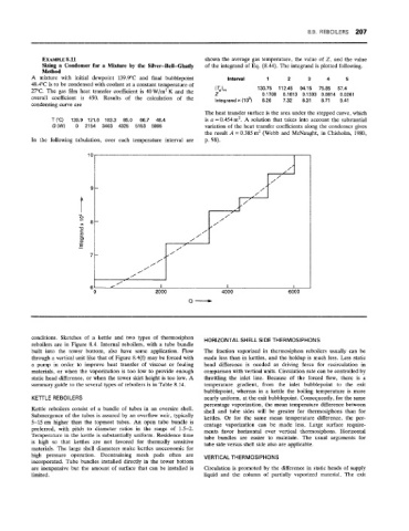
EXAMPLE 8i.11 shown the average gas temperature, the value of Z, and the value
Sizing a Condenser for a Mixture by the Silver-Bell-Ghatly of the integrand of Eq. (8.44). The integrand is plotted following.
Method
A mixture with initial dewpoint 139.9"C and final bubblepoint Interval 1 2 3 5
48.4"C is to be condensed with coolant at a constant temperature of
27°C. The gas film heat transfer coefficient is 40 W/m2 K and the (TJm 130.75 112.45 94.15 75.85 57.4
overall coefficient is 450. Results of the calculation of the 2 0.1708 0.1613 0.1303 0.0814 0.0261
lntegrandx(105)
9.41
8.71
7.32
6.26
8.31
condensing curve are
The heat transfer surface is the area under the stepped curve, which
arc) 139.9 121.6 103.3 85.0 66.7 48.4 is a = 0.454 m2. A solution that takes into account the substantial
e2 (W) 0 2154 3403 4325 5153 5995 variation of the heat transfer coefficients along the condenser gives
the result A = 0.385 mz (Webb and McNaught, in Chisholm, 1980,
In the following tabulation, over each temperature interval are p. 98)
10
9
8
7
6
2000 4000 6000
Q- Q-
conditions. Sketches of a kettle and two types of thermosiphon HORIZONTAL SHELL SIDE THERMOSIPHONS
reboilers are in Figure 8.4. Internal reboilers, with a tube bundle
built into the tower bottom, also have some application. Flow The fraction vaporized in thermosiphon reboilers usually can be
through a vertical unit like that of Figure 8.4(f) may be forced with made less than in kettles, and the holdup is much less. Less static
a pump in order to improve heat transfer of viscous or fouling head difference is needed as driving force for recirculation in
materials, or when the vaporization is too low to provide enough comparison with vertical units. Circulation rate can be controlled by
static head difference, or when the tower skirt height is too low. A throttling the inlet line. Because of the forced flow, there is a
summary guide to the several types of reboilers is in Table 8.14. temperature gradient, from the inlet bubblepoint to the exit
bubblepoint, whereas in a kettle the boiling temperature is more
KETTLE REBOOLEES nearly uniform, at the exit bubblepoint. Consequently, for the same
percentage vaporization, the mean temperatwe difference between
Kettle reboilers consist of a bundle of tubes in an oversize shell. shell and tube sides will be greater for thermosiphons than for
Submergence of the tubes is assured by an ovedow weir, typically kettles. Or for the same mean temperature difference, the per-
5-15cm higher than the topmost tubes. An open tube bundle is centage vaporization can be made less. Large surface require-
preferred, with pitch to diameter ratios in the range of 1.5-2. ments favor horizontal over vertical thermosiphons. Horizontal
Temperature in the kettle is substantially uniform. Residence time tube bundles are easier to maintain. The usual arguments for
is high so that kettles are not favored for thermally sensitive tube side versus shell side also are applicable.
materials. The large shell diameters make kettles uneconomic for
high pressure operation. Deentraining mesh pads often are VERTICAL THERMOSIPHONS
incorporated. Tube bundles installed directly in the tower bottom
are inexpensive but the amount of surface that can be installed is Circulation is promoted by the difference in static heads of supply
limited. liquid and the column of partially vaporized material. The exit