
Page 225 - Chemical Process Equipment - Selection and Design
P. 225
8.7. SHELL-AND-TUBE HEAT EXCHANGERS 195
Forced draft arrangement, from below the tubes, Figure 8.4(h),
develops high turbulence and consequently high heat transfer
coefficients. Escape velocities, however, are low, 3 m/sec or so, and
as a result poor distribution, backmixing and sensitivity to cross
currents can occur. With induced draft from above the tubes, Figure
8.4(g), escape velocities may be of the order of 10 m/sec and better
flow distribution results. This kind of installation is more expensive,
the pressure drops are higher, and the equipment is bathed in hot
air which can be deteriorating. The less solid mounting also can
result in noisier operation.
Correlations for friction factors and heat transfer coefficients
are cited in HEDH. Some overall coefficients based on external
bare tube surfaces are in Tables 8.11 and 8.12. For single passes in
cross flow, temperature correction factors are represented by Figure
83c) for example; charts for multipass flow on the tube side are
given in HEDH and by Kays and London (1984), for example.
Preliminary estimates of air cooler surface requirements can be
made with the aid of Figures 8.9 and 8.10, which are applied in
Example 8.9.
DOUBLE-PIPES
This kind of exchanger consists of a central pipe supported within a
(i) Parallel and counter flows larger one by packing glands [Fig. 8.4(a)]. The straight length is
limited to a maximum of about 20 ft; otherwise the center pipe will
sag and cause poor distribution in the annulus. I: is customary to
operate with the high pressure, high temperature, high density, and
corrosive fluid in the inner pipe and the less demanding one in the
annulus. The inner surface can be provided with scrapers [Fig.
8.4(b)] as in dewaxing of oils or crystallization from solutions.
External longitudinal fins in the annular space can be used to
improve heat transfer with gases or viscous fluids. When greater
heat transfer surfaces are needed, several double-pipes can be
(i i 1 Countercurrent flows stacked in any combination of series or parallel.
Double-pipe exchangers have largely lost out to shell-and-tube
units in recent years, although Walker (1982) lists 70 manufacturers
of them. They may be worth considering in these situations:
1. When the shell-side coefficient is less than half that of the tube
side; the annular side coefficient can be made comparable to the
tube side.
2. Temperature crosses that require multishell shell-and-tube units
[iii) Parallel flows throughout
can be avoided by the inherent true countercurrent flow in
(b) double pipes.
3. High pressures can be accommodated more economically in the
annulus than they can in a larger diameter shell.
In nl 4. At duties requiring only 100-200 sqft of surface the double-pipe
may be more economical, even in comparison with off-the-shelf
units.
The process design of double-pipe exchangers is practically the
simplest heat exchanger problem. Pressure drop calculation is
straightforward. Heat transfer coefficients in annular spaces have
been investigated and equations are cited in Table 8.10. A chapter
is devoted to this equipment by Kern (1950).
8.7. §HELL-AND-TUBE HEAT EXCHANGERS
Such exchangers are made up of a number of tubes in parallel and
(Cii
series through which one fluid travels and enclosed in a shell
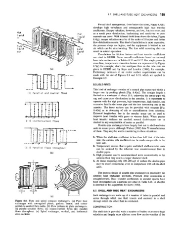
Figure 8.8. Plate and spiral compact exchangers. (a) Plate heat through which the other fluid is conducted.
exchanger with corrugated plates, gaskets, frame, and corner
portals to control flow paths. (b) Flow patterns in plate exchangers, CONSTRUCTION
(i) parallel-counter flows; (ii) countercurrent flows; (iii) parallel
flows throughout. (c) Spiral exchanger, vertical, and horizontal The shell side is provided with a number of baffles to promote high
cross sections. velocities and largely more efficient cross flow on the outsides of the