
Page 222 - Chemical Process Equipment - Selection and Design
P. 222
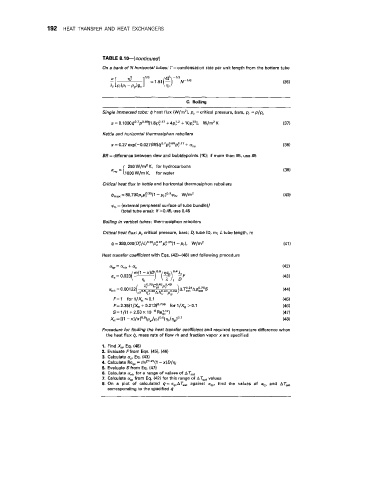
192  HEAT TRANSFER  AND  HEAT  EXCHANGERS


                                   TABLE 8.10-(confinued)
                                   On a bank of N horizontal tubes: r= condensation rate per unit length from the bottom tube


                                                               C.  Boiling
                                   Single immersed tube:  4 heat flux (W/mZ), p,  =critical  pressure, bars, p,  = p/p,
                                      a = 0.1000q0.7p0.69[l .8p?.17 + 4p:.’+   lOp:O],   W/m’  K   (37)
                                   Kettle and horizontal thermosiphon reboilers
                                                               +
                                      a= 0.27 e~p(-O.O27BR)q~.~p~~~p:.’~                       (38)
                                                                an=
                                   BR = difference between dew and bubblepoints (“K);  if more than 85,  use 85
                                      &“C  = [  250 W/m2 K,  for hydrocarbons
                                           1000  W/rn K,   for water

                                   Critical heat flux in kettle and horizontal therrnosiphon reboilers
                                      qmax = 80,700pcp~.35(1 - pr)0.9~b, W/mZ
                                      qb = (external peripheral surface of tube bundle)/
                                         (total tube area); if B0.45,  use 0.45

                                   Boiling in vertical tubes : th er mosi p h on re boi I ers
                                   Critical heat flux: p,  critical pressure,  bars;  Di tube ID,  m;  L tube length, rn
                                                            -
                                                             p,),
                                      4 = 393,000(D~/L)0~35p~1p~~z5(1 W/m’
                                   Heat transfer coefficient with Eqs. (42)-(48) and following procedure
                                      ac=0.023(y7  O.* (  ), 0.4A iF
                                             m(1-x)


                                       F= 1  for 1/X,  50.1
                                       F=2.35(1/Xff  + 0.213)0.736  for I/%,  >0.1
                                       S= 1/(1 + 2.53 x
                                      x,  = [(l - x~/xlo~g~P,/P,~o~5~S//S9~o~1
                                   Procedure for finding the heat transfer coefficient and required temperature  difference when
                                    the heat flux 0,  mass rate of flow m and fraction vapor x are specified
                                   1. Find &, Eq. (48)
                                   2.  Evaluate Ffrom Eqs. (45), (46)
                                   3.  Calculate a=, Eq.  (43)
                                   4.  Calculate Re,   = mF’.25(l - x)D/q,
                                   5.  Evaluate S from Eq.  (47)
                                   6.  Calculate anb for a range of values of AT,,,
                                   7.  Calculate atp from Eq. (42) for this range of AT,,,  values
                                   8.  On  a  plot  of  calculated  q = afpATs,, against  atp, find  the  values  of  atp and  ATsat
                                     corresponding to the specified q