
Page 218 - Chemical Process Equipment - Selection and Design
P. 218
188 HEAT TRANSFER AND HEAT EXCHANGERS
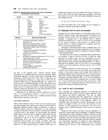
TABLE 8.8. Dimensionless Groups and Units of Quantities realized heat transfer to the heat transfer that would be obtained if
Pertaining to Heat Transfer the fin were at the bare tube temperature throughout. The total
heat transfer is the sum of the heat transfers through the bare and
Symbol Number Group the extended surfaces:
Bi Biot
Fo Fourier
GZ Graetz
Gr Grashof Ab is the tube surface that is not occupied by fins. Example 8.6
Nu Nusselt performs an analysis of this kind of problem.
Pe Peclet
Pr Prandtl
Re Reynolds 8.5. PRESSURE DROP IN HEAT EXCHANGERS
sc Schmidt
St Stanton Although the rate of heat transfer to or from fluids is improved by
increase of linear velocity, such improvements are limited by the
Notation Name and Typical Units economic balance between value of equipment saving and cost of
- ~ ~~ pumping. A practical rule is that pressure drop in vacuum
C heat capacity lBtu/(lb)rF), cal/(g)(”C)] condensers be limited to 0.5-1.0 psi (25-50 Torr) or less, depending
D diameter (ft, rn) on the required upstream process pressure. In liquid service,
9 acceleration of gravity [ft/(hr)’, m/seczl pressure drops of 5-lopsi are employed as a minimum, and up to
G mass velocity [lb/(hr)(ft)’, kg/sec)(m)’] 15% or so of the upstream pressure.
h heat transfer coefficient [Btu/(hr)(sqft)(“F), Calculation of tube-side pressure drop is straightforward, even
~/(m)~(sec)l of vapor-liquid mixtures when their proportions can be estimated.
k thermal conductivity [Btu/(hr)(sqft)(”F/ft), Example 8.7 employs the methods of Chapter 6 for pressure drop in
ca~/~sec~~cm~~~~/cm~~
diffusivity (volumetric) [ft*/hr, cmz/secl a thermosiphon reboiler.
kd
L length (ft, cm) The shell side with a number of segmental baffles presents more
T, AT temperature, temperature difference (“For OR, “Cor K) of a problem. It may be treated as a series of ideal tube banks
U linear velocity (ft/hr, cm/sec) connected by window zones, but also accompanied by some
U overall heat coefficient (same as units of h) bypassing of the tube bundles and leakage through the baffles. A
W mass rate of flow (Ib/hr, g/sec) hand calculation based on this mechanism (ascribed to K.J. Bell) is
P Thermal expansion coefficient (l/”F, 1/”C) illustrated by Ganapathy (1982, pp. 292-302), but the calculation
e time (hr, sec) usually is made with proprietary computer programs, that of HTRI
c1 viscosity [lb/(ft)(hr), g/(crn)(sec)l for instance.
0 densitv Ilb/(ftI3. a/l~m)~l
A simpler method due to Kern (1950, pp. 147-152) nominally
considers only the drop across the tube banks, but actually takes
can exist in any particular case. Transition between modes account of the added pressure drop through baffle windows by
corresponds to a maximum heat flux and the associated critical employing a higher than normal friction factor to evaluate pressure
temperature difference. A table of such data by McAdams (Heat drop across the tube banks. Example 8.8 employs this procedure.
Transmission, McGraw-Hill, New York, 1954, p. 386) shows the According to Taborek (HEDH, 1983, 3.3.2), the Kern predictions
critical temperature differences to range from 42-90°F and the usually are high, and therefore considered safe, by a factor as high
maximum fluxes from 42-126 KBtu/(hr)(sqft) for organic sub- as 2, except in laminar flow where the results are uncertain. In the
stances and up to 410 KBtu/(hr)(sqft) for water; the nature of the case worked out by Ganapathy (1982, pp. 292-302), however, the
surface and any promoters are identified. Equations (40) and (41) of Bell and Kern results are essentially the same.
Table 8.10 are for critical heat fluxes in kettle and thermosyphon
reboilers. Beyond the maximum rate, film boiling develops and the 8.6. TYPES OF HEAT EXCHANGERS
rate of heat transfer drops off very sharply.
Evaluation of the boiling heat transfer coefficient in vertical Heat exchangers are equipment primarily for transferring heat
tubes, as in thermosyphon reboilers, is based on a group of between hot and cold streams. They have separate passages for the
equations, (42)-(48), of Table 8.10. A suitable procedure is listed two streams and operate continuously. They also are called
following these equations in that table. recuperators to distinguish them from regenerators, in which hot
and cold streams pass alternately through the same passages and
EXTENDED SURFACES exchange heat with the mass of the equipment, which is in-
tentionally made with large heat capacity. Recuperators are used
When a film coefficient is low as in the cases of low pressure gases mostly in cryogenic services, and at the other extreme of tem-
and viscous liquids, heat transfer can be improved economically by perature, as high temperature air preheaters. They will not be
employing extended surfaces. Figure 8.6 illustrates a variety of discussed here; a detailed treatment of their theory is by Hausen
extended surfaces. Since the temperature of a fin necessarily (1983).
averages less than that of the bare surface, the effectiveness likewise Being the most widely used kind of process equipment is a
is less than that of bare surface. For many designs, the extended claim that is made easily for heat exchangers. A classified directory
surface may be taken to be 60% as effective as bare surface, but this of manufacturers of heat exchangers by Walker (1982) has several
factor depends on the heat transfer coefficient and thermal hundred items, including about 200 manufacturers of shell-and-tube
conductivity of the fin as well as its geometry. Equations and equipment. The most versatile and widely used exchangers are the
corresponding charts have been developed for the common shell-and-tube types, but various plate and other types are valuable
geometries and are shown, for example, in HEDH (1983, Sec. and economically competitive or superior in some applications.
2.5.3) and elsewhere. One chart is given with Example 8.6. The These other types wilI be discussed briefly, but most of the space
efficiency q of the extended surface is defined as the ratio of a following will be devoted to the shell-and-tube types, primarily