
Page 219 - Chemical Process Equipment - Selection and Design
P. 219
8.6. TYPES OF HEAT EXCHANGERS 189
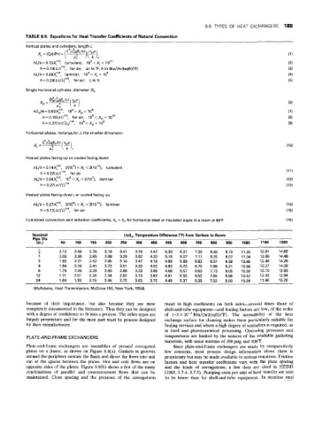
TABLE 8.9. Equiations for Heat Transfer Coefficients of Natural Convection
Vertical plates and cylinders, length L
hL/k=0.13X:/3, turbulent, 109.cXL< IO”
h=0.19(~?~tt)’/~, for air, At in “F, h in Btu/(hr)(sqft)(”F)
h~/k=0.59~:/~, laminar. 1o4<x,< 10’
h= 0.29(At/L)”4, for air, L in ft
Single horizontal cylinder, diameter Do
hD,/k= 0.53Xr, IO3 < X, < IO’
h=0.18(At)7/3, for air, 109<XD
h = 0.27(At/D,)”4, IO4 < X, < IO9
Horizontal plates, irectangular, L the smaller dimension
Heated plates facing up or cooled facing down
hL/k=O.14Xi”, 2(107)<XL<3~10’0), turbulent
h = 0.22(At)”3, for ais
hL/k= O.54Xlf4, lQs<XL <2(107), laminar
h = 0.27(At/L)’”
Heated plates facling down, oh cooled facing up
hL/k= 0.27X:/4, 3(105) <Xi <3(10’’), laminar
h= 0.12iAt/L)1/4, for air
Combined convection and radiation coefficients, h, + h, for horizontal steel or insulated pipes in a room at 80°F
Nominal (At),, Temperature Difference (“F) from Surface to Room
Pipe Dia
[in.) 50 100 150 200 250 300 400 500 600 700 800 900 1000 1100 1200
~ ~
~ ~ ~~ ~
1 -
2 2.12 2.48 2.76 3.10 3.41 3.75 4.47 5.30 6.21 7.25 8.40 9.73 11.20 12.81 14.65
1 2.03 2.38 2.65 2.98 3.29 3.62 4.33 5.16 6.07 7.11 8.25 9.57 11.04 12.65 14.48
2 1.93 2.27 2.52 2.85 3.14 3.47 4.18 4.99 5.89 6.92 8.07 9.38 10.85 12.46 14.28
4 1.84 2.16 2.41 2.72 3.01 3.33 4.02 4.83 5.72 6.75 7.89 9.21 10.66 12.27 14.09
8 1.76 2.06 2.29 2.60 2.89 3.20 3.88 4.68 5.57 6.60 7.73 9.05 10.50 12.10 13.93
12 1.71 2.01 2.24 2.54 2.82 3.13 3.83 4.61 5.50 6.52 7.65 8.96 10.42 12.03 13.84
24 1.64 1.93 2.15 2.45 2.72 3.03 3.70 4.48 5.37 6.39 7.52 8.83 10.28 11.90 13.70
~____
(McAdams, Heat Transmission, McGraw-Hill, New York, 1954).
because of their importance, but also because they are most result in high coefficients on both sides-several times those of
completely documented in the literature. Thus they can be designed shell-and-tube equipment-and fouling factors are low, of the order
with a degree of confidence to fit into a process. The other types are of 1-5 X lo-’ Btu/(hr)(sqft)(“F). The accessibility of the heat
largely proprietary and for the most part must be process designed exchange surface for cleaning makes them particularly suitable for
by their manufacturers. fouling services and where a high degree of sanitation is required, as
in food and pharmaceutical processing. Operating pressures and
E-AND-FRAME EXCHANGERS temperatures are limited by the natures of the available gasketing
materials, with usual maxima of 300 psig and 400°F.
Plate-and-frame exchangers are assemblies of pressed Corrugated Since plate-and-frame exchangers are made by comparatively
plates on a frame, as shown on Figure 8.8(a). Gaskets in grooves few concerns, most process design information about them is
around theperiphery contain the fluids and direct the flows into and proprietary but may be made available to serious enquirers. Friction
out of the spaces between the plates. Hot and cold flows are on factors and heat transfer coefficients vary with the plate spacing
opposite sides of the plates. Figure 8.8(b) shows a few of the many and the kinds of corrugations; a few data are cited in HEDH
combinations of parallel and countercui-rent flows that can be (1983, 3.7.4-3.7.5). Pumping costs per unit of heat transfer are said
maintained. Close spacing and the presence of the corrugations to be lower than for shell-and-tube equipment. In stainless steel