
Page 224 - Chemical Process Equipment - Selection and Design
P. 224
194 HEAT TRANSFER AND HEAT EXCHANGERS
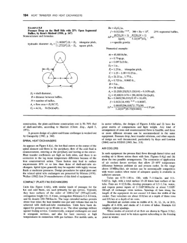
EXAMPLE 8.8 Re = Dh G, /a
Pressure Drop on the Shell Side with 25% Open Segmental f = 0.0121Re-0.19, 300 <Re < lo6, 25% segmental baffles,
Bafiies, by Kern’s Method (1950, p. 147)
Nomenclature and formulas: fG,2Ds(N + 1) -fGSD,(N - + 1)
AP = 2gp& 5.22(1010)sD, ’ psi’
1. 1028P:/D, - Dt, triangular pitch, s = specific gravity.
hydraulic diameter Dh =
1.2732P:/Dt - Dt, square pitch,
Numerical example:
Q rh = 43,800 lb/hr,
s = 0.73 sp gr,
y = 0.097 lb/ft hr,
D, = 1 in.,
\
\ Pt= 1.25 in., triangular pitch,
C = 1.25 - 1.00 = 0.25 in.,
D, = 21.25 in., 1.77 ft.,
Dh = 0.723 in., 0.0603 ft.,
B=5in.,
F P 1 - - i N = 38 baffles,
A, = 21.25(0.25)(5)/1.25(144) = 0.1476 sqft,
D, = shell diameter, G, = 43,800/0.1476 = 296,810 lb/(hr)(sqft),
B = distance between baffles, Re = 0.0603(296,810)/0.97 = 18,450,
N = number of baffles, f = 0.0121(18,450)-0.19 = 0.00187,
A, =flow area = D,BC/P,, 0.00187(296,810)’(1.77)(39) = 4,95 psi,
C, = m/A,, lb/(hr)(sqft), AP = 5.22( lo1’) (0.73)(0.0603)
construction, the plate-and-frame construction cost is 50-70% that in motor vehicles, the designs of Figures 8.6(h) and (i) have the
of shell-and-tube, according to Marriott (Chern. Eng., April 5, great merits of compactness. and light weight. Any kind of
1971). arrangement of cross and countercurrent flows is feasible, and three
A process design of a plate-and-frame exchanger is worked out or more different streams can be accommodated in the same
by Ganapathy (1982, p. 368). equipment. Pressure drop, heat transfer relations, and other aspects
of design are well documented, particularly by Kays and London
SPIRAL HEAT EXCHANGERS
(1984) and in HEDH (1983, Sec. 3.9).
As appears on Figure 8.8(c), the hot fluid enters at the center of the
spiral element and flows to the periphery; flow of the cold fluid is AIR COOLERS
countercurrent, entering at the periphery and leaving at the center. In such equipment the process fluid flows through finned tubes and
Heat transfer coefficients are high on both sides, and there is no cooling air is blown across them with fans. Figures 8.4(g) and (h)
correction to the log mean temperature difference because of the show the two possible arrangements. The economics of application
true countercurrent action. These factors may lead to surface of air coolers favors services that allow 25-40°F temperature
requirements 20% or so less than those of shell-and-tube ex- difference between ambient air and process outlet. In the range
changers. Spiral types generally may be superior with highly viscous above 10 MBtu/(hr), air coolers can be economically competitive
fluids at moderate pressures. Design procedures for spiral plate and with water coolers when water of adequate quality is available in
the related spiral tube exchangers are presented by Minton (1970). sufficient amount.
Walker (1982) lists 24 manufacturers of this kind of equipment. Tubes are 0.75-1.00in. OD, with 7-11fins/in. and 0.5-
COMPACT (PLATE-FIN) EXCHANGERS 0.625 in. high, with a total surface 15-20 times bare surface of the
tube. Fans are 4-12 ft/dia, develop pressures of 0.5-1.5 in. water,
Units like Figure 8.6(h), with similar kinds of passages for the and require power inputs of 2-5HP/MBtu/hr or about 7.5HP/
hot and cold fluids, are used primarily for gas service. Typically lOOsqft of exchanger cross section. Spacings of fans along the
they have surfaces of the order of 1200mz/m3 (353sqft/cuft), length of the equipment do not exceed 1.8 times the width of the
corrugation height 3.8-11.8 mm, corrugation thickness 0.2-0.6 mm, cooler. Face velocities are about 10 ft/sec at a depth of three rows
and fin density 230-700 fins/m. The large extended surface permits and 8 ft/sec at a depth of six rows.
about four times the heat transfer rate per unit volume that can be Standard air coolers come in widths of 8, 10, 12, 16, or 20ft,
achieved with shell-and-tube construction. Units have been de- lengths of 4-40ft, and stacks of 3-6 rows of tubes. Example 8.8
signed for pressures up to 80 atm or so. The close spacings militate employs typical spacings.
against fouling service. Commercially, compact exchangers are used Three modes of control of air flow are shown in Figure 3.3(e).
in cryogenic services, and also for heat recovery at high Precautions may need to be taken against subcooliig to the freezing
temperatures in connection with gas turbines. For mobile units, as point in winter.