
Page 276 - Chemical Process Equipment - Selection and Design
P. 276
9.5. CONTINUOUS TRAY AND CONVEYOR BELT DRYERS
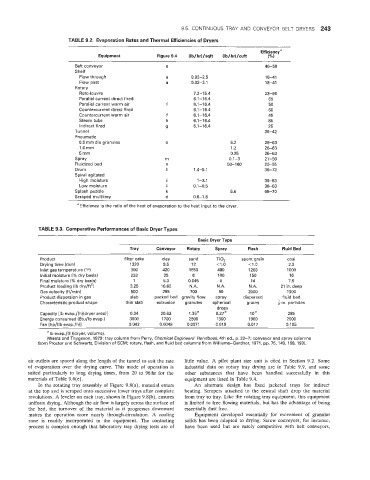
TABLE 9.2. Ewaporatian Rates and Thermal Efficiencies of Dryers
Efficiency"
Equipment Figure 9.4 (Ib/hr)/sqft (Ib/hr)/cuft (%)
Belt conveyor e 46-58
Shelf
Flow through a 0.02-2.5 18-41
Flow past a 0.02-3.1 18-41
Rotary
Roto-louvre 7.2-15.4 23-66
Parallel current direct fired 6.1-16.4 65
Paraliel current warm air f 6.1 -1 6.4 50
Countercurrent direct fired 6.1 -1 6.4 60
Countercurrent warm air f 6.1 -1 6.4 45
Steam tube h 6.1-16.4 85
Indirect fired 9 6.1-16.4 25
Tunnel 36-42
Pneumatic
0.5 mm dia granules 0 6.2 26-63
1.0 rnm 1.2 26-63
5 mm 0.25 26-63
Spray rn 0.1-3 21-50
Fluidized bed n 50-1 60 20-55
Drum I 1.4-5.1 36-73
Spiral agitated
High moisture i 1-3.1 36-63
Low moisture I 0.1-0.5 36-63
Splash paddle k 5.6 65-70
Scraoed multitrav d 0.8-1.6
a Efficiency is the ratio of the heat of evaporation to the heat input to the dryer.
TABLE 9.3. Comparative Performances of Basic Dryer Types
Basic Dryer Type
Tray Conveyor Rotary Spray Flash Fluid Bed
Product filter cake clay sand TiO, spent grain coal
Drying time (minl 1320 9.5 12 <1 .o <I .o 2.0
inlet gas temperature (OF) 300 420 1650 490 1200 1000
Initial moisture (% dry basis) 233 25 6 100 150 16
Final moisture (% dry basis) 1 5.3 0.045 0 14 7.5
Product loaiding (Ib dry/ftz) 3.25 16.60 N.A. N.A. N.A. 21 in. deep
Gas velocity (ftJmin) 500 295 700 50 2000 1000
Product dispersion in gas slab packed bed gravity flow spray dispersed fluid bed
7 .
Characteristic product shape thin slab extrusion granules spherical grains F-in. particles
drops
Capacity [It] evap./(h)(dryer areall 0.34 20.63 1 .35" 0.27" loa 285
Energy consumed (Btu/fb evap.) 3000 1700 2500 1300 1900 2000
Fan Ihd(lb evaD./h)l 0.042 0.0049 0.0071 0.019 0.087 0.105
a Ib evap./(h)(dryer, volume).
(Wentz and Thygeson, 1979: tray column from Perry, Chemical Engineers' Handbook, 4th ed., p. 20-7; conveyor and spray columns
from Proctor and Schwartz, Division of SCM; rotary, flash, and fluid bed columns from Williams-Gardner, 1971, pp. 75, 149, 168, 193).
air outlets are spaced along the length of the tunnel to suit the rate little value. A pilot plant size unit is cited in Section 9.2. Some
of evaporation over the drying curve. This mode of operation is industrial data on rotary tray drying are in Table 9.9, and some
suited particularly to long drying times, from 20 to 96 hr for the other substances that have been handled successfully in this
materials of Table 9.6(e). equipment are listed in Table 9.4.
In the rotating tray assembly of Figure 9.8(a), material enters An alternate design has fixed jacketed trays for indirect
at the top and is scraped onto successive lower trays after complete heating. Scrapers attached to the central shaft drop the material
revolutions. A leveler on each tray, shown in Figure 9.8(b), ensures from tray to tray. Like the rotating tray equipment, this equipment
miform drying. Although the air flow is largely across the surface of is limited to free flowing materials, but has the advantage of being
the bed, the turnover of the material as it progresses downward essentially dust free.
makes the operation more nearly through-circulation. A cooling Equipment developed essentially for movement of granular
zone is readily incorporated in the equipment. The contacting solids has been adapted to drying. Screw conveyors, for instance,
process is complex enough that Iaboratory tray drying tests are of have been used but are rarely competitive with belt conveyors,