
Page 280 - Chemical Process Equipment - Selection and Design
P. 280
9.6. ROTARY CYLINDRICAL DRYERS 247
Air exhaust
IHeat soured 4 Fan 9.6. ROTARY CYLINDRICAL DRYERS
I
Rotating cylindrical dryers are suited for free-flowing granular
materials that require drying times of the order of 1 hr or less.
Materials that tend to agglomerate because of wetness may be
preconditioned by mixing with recycled dry product.
Such equipment consists of a cylindrical shell into which the
wet material is charged at one end and dry material leaves at the
other end. Figure 9.9 shows Some examples. Drying is accomplished
by contact with hot gases in parallel or countercurrent AQW or with
heat transfer through heated tubes or double shells. Designs are
available in which the tubes rotate with the shell or are faxed in
space.
Diameters typically are 4-10 ft and lengths are 4-15 diameters.
The product of rpm and diameter is typically between 25 and 35.
Superficial gas velocities are 5-10 ft/sec; but lower values may be
Track
‘chamber 1 needed for fine products, and rates up to 35 ft/sec may be allowable
for coarse materials. To promote longitudinal travel of the solid, the
(a) shell is mounted on a slope of 1 in 40 or 20.
In a countercurrent dryer the exit temperature of the solid
approaches that of the inlet gas. In a parallel current dryer, the exit
gas is 10-20°C above that of the solid. For design purposes the
temperature of the exit solid in parallel flow may be taken as 100°C.
Flights attached to the shell lift up the material and shower it as
a curtain through which the gas flows. Cross sections of some dryers
are shown in Figure 9.10. The shape of flights is a compromise
between effectiveness and ease of cleaning. The number is between
2 and 4 times the diameter of the shell in feet, and their depth is
between & and & of the diameter. Holdup in the dryer depends on
details of design and operation, but ’74% is a usual figure.
Cross-sectional holdup is larger at the wet end than at the dry end.
An 85% free cross section commonly is adopted for design
purposes; the rest is taken up by ilights and settled and cascading
solids.
Residence time depends on the nature of the material and
($1 mechanical features of the dryer. The performance data of Table
9.10 show a range of 7-90min. A formula cited by Williams-
ET AIR Gardner (1971, p. 133) for the geometrical residence dime is
,HAUST
HEATING PIPFS 8 = kL/nDS, (9.17)
where L is the length, D is the diameter, It is rpm, and S is the slope
/i (in./ft). The coefficient k varies from 3 to 12 for various
countercurrent single shell dryers. The formula may be of some
DRYAIR,)
BLOWER/
INTAKE
value in predicting roughly the effects of changes in the quantities
\END ENTRANGE SIDE EXIT FOR INDIRECT HEATING included in it.
FOR WETTRUGKS DRY TRUCKS SYSTEM
The only safe way of designing a rotary dryer is based on pilot
plant tests or by comparison with known performance of similar
operations. Example 9.5 utilizes pilot plant data for upscaling a
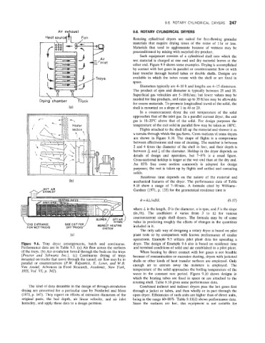
Figure 9.6. Tiray dryer arrangements, batch and continuous. dryer. The design of Example 9.6 also is based on residence time
Performance data are in Table 9.5. (a) Air flow across the surfaces and terminal conditions of solid and air established in a pilot plant.
of the trays. (b) Air circulation forced through the beds on the trays When heating by direct contact with hot gases is not feasible
(Proctor and Schwartz Znc.) (c) Continuous drying of trays because of contamination or excessive dusting, dryers with jacketed
mounted on trucks that move through the tunnel; air flow may be in shells or other kinds of heat transfer surfaces are employed. Only
parallel or couintercurrent (P.W. Kilpatrick, E. Lowe, and W.B.
Van Arsdel, Advances in Food Research, Academic, New York, enough air to entrain away the moisture is employed. The
temperature of the solid approaches the boiling temperature of the
1955, Vol. VZ, p. 342).
water in the constant rate period. Figure 9.10 shows designs in
which the heating tubes are fixed in space or are attached to the
rotating shell. Table 9.10 gives some performance data.
The kind of data desirable in the design of through-circulation Combined indirect and indirect dryers pass the hot gases first
drying are presented for a particular case by Nonhebel and Moss through a jacket or tubes, and then wholly or in part through the
(1971, p. 147). They report on effects of extrusion diameters of the open dryer. Efficiencies of such units are higher than of direct units,
original paste, the bed depth, air linear velocity, and air inlet being in the range 60-80%. Table 9.10(d) shows performance data.
humidity, and apply these data to a design problem. Since the surfaces are hot, this equipment is not suitable for