
Page 355 - Chemical Process Equipment - Selection and Design
P. 355
318 SOLID-LIQUID SEPARATION
10
09
1 X X
08 >
0 80 X
07 X X
X
X
0 7c
OE
0 A
p 05
_I
a
01
0:
J 0
Oi p./
!" 0
0'
C I I I I I I I I I
01 02 03 OL 05 06 C7 08 09
XlL----
(a)
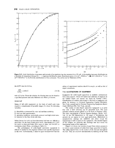
Figure 11.5. Axial distribution of pressure and porosity of an ignition-plug clay measured in a CP cell. (a) Normalized pressure distribution as
a function of normalized distance [(- - -) experimental filtration data; theoretical curves: (X) AP = 98 kN m-'; (0) AP = 294 kN m-'; (A)
AP = 883 kN m-'1. (b) Porosity distributions at three pressures. The curves are by Wakeman (1978).
the SCFT data for 0.01 m, advice of experienced vendors should be sought, as well as that of
expert consultants.
A Pt
-- - (lOOL)', (1 1.28)
0. 67tF 11.6. ILLUSTRATIONS OF EQUIPMENT
with AP in bar. From this relation the filtering time can be found at Equipment for solid-liquid separation is available commercially
a specified pressure and cake thickness and when tF is known. from many sources. About 150 names and addresses of suppliers in
the United States and abroad are listed by Purchas (1981).
SCALE-UP Classifications of vendors with respect to the kind of equipment are
given, for instance, in Chemical Engineering Catalog (Reinhold,
Sizing of full scale equipment on the basis of small scale tests New York, annual) and in Chemical Engineering Equipment Buyers
requires a consideration of possible ranges of at least the following Guide (McGraw-Hill, New York, annual).
variables: The variety of solid-liquid separation equipment is so great
that only a brief selection can be presented here. The most
1. filterability as measured by cake and medium resistivity; extensive modern picture gallery is in the book of Purchas (1981).
2. feed rate and concentration; The older encyclopedia of Kieser (Spamer-Springer, Berlin, 1937,
3. operating conditions, particularly pressure and high initial rates; Vol. 2) has 250 illustrations in 130 pages of descriptions; the
4. behavior of the filter cloth with time. pictures do not appear to have aged particularly. Illustrations in
manufacturers catalogs are definitive and often reveal the
Safety factors for scale up from laboratory leaf tests are difficult to functioning as well as aspect of the equipment. The selected figures
generalize. On the basis of pilot plant work, adjustments of 11-21% of this chapter are primarily line drawings that best reveal the
are made to plate-and-frame filter areas or rates, and 14-20% to functioning modes of the equipment.
continuous rotary filters, according to Table 1.4. Figure 11.9 shows two models of sand filters whose purpose is
The performance of solid-liquid separation equipment is to remove small contents of solids from large quantities of liquids.
difficult to predict by the engineer without some specific experience The solids deposit both on the surface of the bed and throughout
in this area. Unfortunately, it must be again recommended that the the bed. They are removed intermittently by shutting off the main