
Page 357 - Chemical Process Equipment - Selection and Design
P. 357
320 SOLID-LIQUID SEPARATION
Rotating mechanism TABLE 11.9. Performances of Sedimentation Equipment
(a) Thickenersa
% solids Unit area,
sq. ft./ton,
Feed Underflow dav
Alumina, Bayer process:
Red-mud primary settlers 3-4 10-25 20-30
Red-mud washers 6-8 15-20 10-15
Red-mud final thickener 6-8 20-35 10-15
Trihydrate seed thickener 2-8 30-50 12-30
Cement, West process 16-20 60-70 15-25
Cement kiln dust 9-10 45-55 3-18
(a) e Thick sludge discharge Coral 12-18 45-55 15-25
Cyanide slimes 16-33 40-55 5-13
Lime mud:
b) Flocculant control Acetylene generator 12-1 5 30-40 15-33
valve \
Lime-soda process 9-1 1 35-45 15-25
Paper industry 8-10 32-45 14-18
Feed ccntrol
Magnesium hydroxide from brine 8-10 25-50 60-100
Metallurgical (flotation or gravity
concentration):
Copper concentrates 14-50 40-75 2-20
Copper tailings 10-30 45-65 4-10
Baffled feed Lead concentrates 20-25 60-80 7-18
Zinc concentrates 10-20 50-60 3-7
Nickel:
Leached residue 20 60 8
Sulfide concentrate 3-5 65 25
Potash slimes 1-5 6-25 40-1 25
Uranium:
Cent Clarif ied <dater Acid leached ore 10-30 25-65 2-10
curt Alkaline leached ore 20 60 10
Uranium precipitate 1-2 10-25 50-1 25
(b) Clarifiers
Overflow rate, Detention time,
Application gal./min., sq. ft. hr.
Primary sewage treatment
(settleable-solids removal) 0.4 2
Secondary sewage treatment (final
clarifiers-activated sludge and
trickling filters) 0.55-0.7 1.5-2
Water clarification (following 30-
min. flocculation) 0.4-0.55 3
Lime and lime-soda softening (high
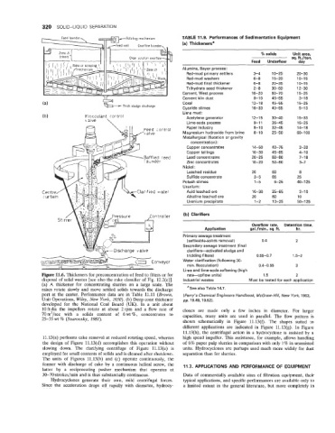
Figure 11.6. Thickeners for preconcentration of feed to filters or for rate-upflow units) 1.5 2
disposal of solid wastes [see also the rake classifier of Fig. 12.2(e)J. Industrial wastes Must be tested for each application
(a) A thickener for concentrating slurries on a large scale. The
rakes rotate slowly and move settled solids towards the discharge aSee also Table 14.7.
port at the center. Performance data are in Table 11.11 (Brown, (Perry’s Chemical Engineers Handbook, McGraw-Hill, New York, 1963,
Unit Operations, Wiley, New York, 2950). (b) Deep cone thickener pp. 19.49,19.52).
developed for the National Coal Board (UK). In a unit about
10ftdia the impellers rotate at about 2rpm and a flow rate of clones are made only a few inches in diameter. For larger
70 m3/sec with a solids content of 6 wt %, concentrates to capacities, many units are used in parallel. The flow pattern is
25-35 wt % (Svarovsky, 2982).
shown schematically in Figure 11.13(f). The shapes suited to
different applications are indicated in Figure 11.13(g). In Figure
ll.l3(h), the centrifugal action in a hydrocyclone is assisted by a
11.13(a) performs cake removal at reduced rotating speed, whereas high speed impeller. This assistance, for example, allows handling
the design of Figure 11.13(d) accomplishes this operation without of 6% paper pulp slurries in comparison with only 1% in unassisted
slowing down. The clarifying centrifuge of Figure 11.13(e) is units. Hydrocyclones are perhaps used much more widely for dust
employed for small contents of solids and is cleaned after shutdown. separation than for slurries.
The units of Figures 11.13(b) and (c) operate continuously, the
former with discharge of cake by a continuous helical screw, the 11.7. APPLICATIONS AND PERFORMANCE OF EQUIPMENT
latter by a reciprocating pusher mechanism that operates at
30-70 strokes/min and is thus substantially continuous. Data of commercially available sizes of filtration equipment, their
Hydrocyclones generate their own, mild centrifugal forces. typical applications, and specific performances are available only to
Since the acceleration drops off rapidly with diameter, hydrocy- a liited extent in the general literature, but more completely in