
Page 356 - Chemical Process Equipment - Selection and Design
P. 356
11.6. ILLUSTRATIONS OF EQUIPMENT 319
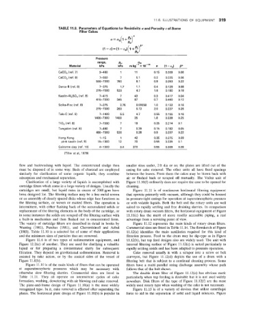
TABLE 11.8. Parameters of Equations for Resistivity a and Porosity E of Some
Filter Cakes a! = no(, + z)"
(1 -E) = (1 - qJ(l +g*
Pressure
range, Pa, a0.
Material kPa kPa rn kg-' X IO-" n (1 -En) B*
CaCO, (ref. 7) 3-480 1 11 0.15 0.209 0.06
CaCO, (ref. 8) 7-550 7 5.1 0.2 0.225 0.06
550-7000 790 8.1 0.9 0.263 0.22
Darco-B (ref. 8) 7-275 1.7 1.1 0.4 0.129 0.08
275-7000 520 4.7 1.8 0.180 0.18
Kaolin-AI,SO, (ref. 8) 7-41 5 7 43 0.3 0.417 0.04
415-7000 345 87 0.7 0.460 0.12
Solka-Floc (ref. 8) 7-275 2.75 0.00058 1.0 0.132 0.16
275-7000 260 0.13 2.0 0.237 0.26
Talc-C (ref. 8) 7-1400 5.5 4.7 0.55 0.155 0.16
1400-7000 1400 35 1.8 0.339 0.25
TiO, (ref. 8) 7-7000 7 18 0.35 0.214 0.1
Tungsten (ref. 8) 7-480 7 0.39 0.15 0.182 0.05
480-7000 520 0.38 0.9 0.207 0.22
Hong Kong 1-15 1 42 0.35 0.275 0.09
pink kaolin (ref. 9) 15-1000 12 70 0.55 0.335 0.1
Gairome clay (ref. 10) 4-1000 3.4 370 0.55 0.309 0.09
(Tiller et al, 4979)
flow and backwashing with liquid. The concentrated sludge then smaller sizes under, 2ft dia or so; the plates are lifted out of the
must be disposed of in some way. Beds of charcoal are employed casing for cake removal. The other units all have fixed spacings
similarly for clarification of some organic liquids; they combine between the leaves. From them the cakes may be blown back with
adsorption and mecharical separation. air or flushed back or scraped off manually. The VaIlez unit of
Clarification of a large variety of liquids is accomplished with Figure 11.10(f) ordinarily does not require the case to be opened for
cartridge filters which come in a large variety of designs. Usually the cleaning.
cartridges are small, but liquid rates in excess of 5000gpm have Figure 11.11 is of continuous horizontal filtering equipment
been designed for. The filtering surface may be a fine metal screen that operate primarily with vacuum, although they could be housed
or an assembly of closely spaced disks whose edge face functions as in pressure-tight casings for operation at superatmospheric pressure
the filtering surface, or woven or matted fibers. The operation is or with volatile liquids. Both the belt and the rotary units are well
intermittent, with either flushing back of the accumulated solids or suited to rapidly settling and free draining slurries. In comparison
replacement of the filtering elements in the body of the cartridge, or with rotary drum vacuum filters, the horizontal equipment of Figure
in some instances the solids are scraped off the filtering surface with ll.ll(c) has the merit of more readily accessible piping, a real
a built-in mechanism and then flushed out in concentrated form. advantage from a servicing point of view.
The variety of cartridge filters are described in detail in books by Figure 11.12 represents the main kinds of rotary drum filters.
Warring (1981), Purchas (1981), and Cheremisinoff and Azbel Commercial sizes are listed in Table 11.14. The flowsketch of Figure
(1983). Table 11.10 is a selected list of some of their applications 11.12(a) identifies the main auxiliaries required for this kind of
and the rrainimuim sizes of particles that are removed. Filtration process. Feed to the drum may be dip-type as in Figure
Figure 11.6 is of two types of sedimentation equipment, and 11.12(b), but top feed designs also are widely used. The unit with
Figure 12.2(e) of another. They are used for clarifying a valuable internal filtering surface of Figure 11.12(c) is suited particularly to
liquid or for preparing a concentrated slurry for subsequent rapidly settling solids and has been adapted to pressure operation.
filtration. They depend on gravitational sedimentation. Removal is Cake removal usually is with a scraper into a screw or belt
assisted by rake action, or by the conical sides of the vessel of conveyor, but Figure 11.12(d) depicts the use of a drum with a
Figure llh(b). filtering belt that is subject to a continual cleaning process. Some
Figure 11.10 is of the main kinds of filters that can be operated filters have a multi parallel string discharge assembly whose path
at superatmospheric pressures which may be necessary with follows that of the belt shown.
otherwise slow filtering slurries. Commercial sizes are listed in The double drum filter of Figure 11.12(e) has obvious merit
Table 11.11. They all operate on intermittent cycles of cake particularly when top feeding is desirable but it is not used widely
formation, washing, dewatering with air blowing and cake removal. nowadays. Disk filters of the type of Figure 11.12(f) are the most
The plate-and-frame design of Figure 11.10(a) is the most widely widely used rotary type when washing of the cake is not necessary.
recognized type. In it, cake removal is effected after separating the Figure 11.13 is of a variety of devices that utilize centrifugal
plates. The horizontal plate design of Figure 11.10(b) is popular in force to aid in the separation of solid and Piquid mixtures. Figure