
Page 196 - Chemical engineering design
P. 196
173
FLOW-SHEETING
streams; for example, a distillation column divides the components in the feed between
the overhead and bottom product streams, and any side streams. It is therefore conve-
nient, when setting up the equations describing a unit operation, to express the flow of
any component in any outlet stream as a fraction of the flow of that component in the
inlet stream.
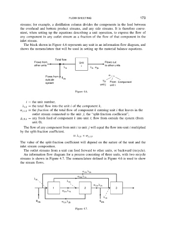
The block shown in Figure 4.6 represents any unit in an information flow diagram, and
shows the nomenclature that will be used in setting up the material balance equations.
Total flow
Flows from Unit Flows out
other units i to other units
λ ik λ ik . α jik
α
Flows from g j i k
outside i0k To
system From Component
unit j unit i
Figure 4.6.
i D the unit number,
i,k D the total flow into the unit i of the component k,
˛ j,i,k D the fraction of the total flow of component k entering unit i that leaves in the
outlet stream connected to the unit j; the “split-fraction coefficient”,
g i,0,k D any fresh feed of component k into unit i; flow from outside the system (from
unit 0).
The flow of any component from unit i to unit j will equal the flow into unit i multiplied
by the split-fraction coefficient.
D i,k ð ˛ j,i,k
The value of the split-fraction coefficient will depend on the nature of the unit and the
inlet stream composition.
The outlet streams from a unit can feed forward to other units, or backward (recycle).
An information flow diagram for a process consisting of three units, with two recycle
streams is shown in Figure 4.7. The nomenclature defined in Figure 4.6 is used to show
the stream flows.
α 13k λ 3k
α λ
λ 1k 31k 1k
λ 2k
α 32k λ 2k
1 2 3
α 21k λ 1k
λ 3k
g α λ g
10k 12k 2k 30k
Figure 4.7.