
Page 200 - Chemical engineering design
P. 200
FLOW-SHEETING
H
Alcohol feed
product
vent Water Acetone Water 177
Reactor Condenser Scrubber Coln 1 Coln 2
1 2 3 4 5
Bypass
Recycle
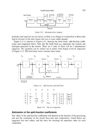
Figure 4.12. Information flow diagram
preheater and vaporiser are not shown, as there is no change in composition in these units
and no division of the inlet stream into two or more outlet streams.
Figure 4.12 is redrawn in Figure 4.13, showing the fresh feeds, split-fraction coeffi-
cients and component flows. Note that the fresh feed g 20k represents the acetone and
hydrogen generated in the reactor. There are 5 units so there will be 5 simultaneous
equations. The equations can be written out in matrix form (Figure 4.14) by inspection
of Figure 4.13. The fresh feed vector contains three terms.
λ 1k λ 2k λ 3k λ 4k λ 5k
α 21k λ 1k α 32k λ 2k α 43k λ 3k α 54k λ 4k
A B C D E
1 2 3 4 5
g
10k
α 42k λ 2k
g
20k
Acetone
{ } g 30k {Water} α 15k λ 5k
hydrogen
{ }
Isopropyl
alcohol
Figure 4.13. Split-fractions and fresh feeds
1 2 3 4 5
1 1 0 0 0 ˛ 15k 1k g 10k
2 ˛ 21k 1 0 0 0 2k g 20k
3 0 ˛ 32k 1 0 0
ð 3k D g 30k
4 0 ˛ 42k ˛ 43k 1 0 0
4k
5 0 0 0 ˛ 54k 1 0
5k
Figure 4.14. The set of equations
Estimation of the split-fraction coefficients
The values of the split-fraction coefficients will depend on the function of the processing
unit and the constraints on the stream flow-rates and compositions. Listed below are
suggested first trial values, and the basis for selecting the particular value for each
component.