Page 205 - Chemical engineering design
P. 205

182
                                                        CHEMICAL ENGINEERING
                             Step 5: Use the equation solving routine (E-solve with AS-EASY-AS) to solve the
                           equations and put the results, the flows into each unit, into a column headed “flows”,
                           column H in Figure 4.17; repeat for each component matrix.
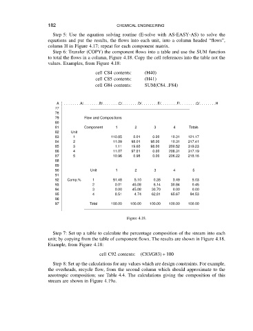
                             Step 6: Transfer (COPY) the component flows into a table and use the SUM function
                           to total the flows in a column, Figure 4.18. Copy the cell references into the table not the
                           values. Examples, from Figure 4.18:
                                               cell C84 contents:   (H40)
                                               cell C85 contents:   (H41)
                                               cell G84 contents:   SUM(C84..F84)


                               A] . ... .. ..A/... .. ...B/... .. .. .C/... .. .. .D/... .. .. .E/.. ... .. .F/.. .. ... .G/.. .. ... .H
                              77
                              78
                              79          Flow and Compositions
                              80
                              81          Component     1       2       3       4     Totals
                              82     Unit
                              83      1               110.85   0.01    0.00    10.31  121.17
                              84      2                11.09  98.01   98.00    10.31  217.41
                              85      3                1.11   19.60   98.00   200.52  319.23
                              86      4                11.07  97.81    0.00   208.31  317.19
                              87      5                10.96   0.98    0.00   206.22  218.16
                              88
                              89
                              90             Unit       1       2       3       4       5
                              91
                              92   Comp.%     1        91.48   5.10    0.35     3.49    5.03
                              93              2        0.01    45.08   6.14    30.84    0.45
                              94              3        0.00    45.08   30.70    0.00    0.00
                              95              4        8.51    4.74    62.81   65.67   94.53
                              96
                              97             Total    100.00  100.00  100.00  100.00  100.00

                                                            Figure 4.18.


                             Step 7: Set up a table to calculate the percentage composition of the stream into each
                           unit; by copying from the table of component flows. The results are shown in Figure 4.18.
                           Example, from Figure 4.18:

                                                 cell C92 contents:  (C83/G83) Ł 100
                             Step 8: Set up the calculations for any values which are design constraints. For example,
                           the overheads, recycle flow, from the second column which should approximate to the
                           azeotropic composition; see Table 4.4. The calculations giving the composition of this
                           stream are shown in Figure 4.19a.
   200   201   202   203   204   205   206   207   208   209   210