
Page 210 - Chemical engineering design
P. 210
For a column with no side streams the fraction of the total feed flow going to the
overheads is given by: FLOW-SHEETING 187
x fk x wk
r overheads D
x dk x wk
where x is the component composition and the suffixes f, d, w refer to feed, overheads
and bottoms respectively.
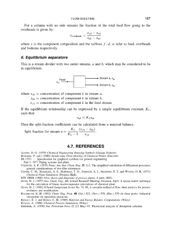
6. Equilibrium separators
This is a stream divider with two outlet streams, a and b, which may be considered to be
in equilibrium.
Stream a, x
Feed ak
x fk
Stream b, x bk
where x ak D concentration of component k in stream a,
x bk D concentration of component k in stream b,
x fk D concentration of component k in the feed stream.
If the equilibrium relationship can be expressed by a simple equilibrium constant, K k ,
such that:
x ak D K k x bk
Then the split-fraction coefficients can be calculated from a material balance.
K k x fk x bk
Split fraction for stream a D .
K k 1 x fk
4.7. REFERENCES
AUSTIN, D. G. (1979) Chemical Engineering Drawing Symbols (George Godwin).
BENEDEK, P. (ed.) (1980) Steady-state Flow-sheeting of Chemical Plants (Elsevier).
BS 1553: ... Specification for graphical symbols for general engineering
Part 1: 1977 Piping systems and plant.
COLBURN, A. P. (1939) Trans. Am. Inst. Chem. Eng. 35, 211. The simplified calculation of diffusional processes,
general considerations of two-film resistances.
CROWE,C. M., HAMIELEE,A. E.,HOFFMAN,T. N., JOHNSON,A.I., SHANNON,P.T. and WOODS, D. R. (1971)
Chemical Plant Simulation (Prentice-Hall).
DIN 28004 (1988) Flow sheets and diagrams of process plants, 4 parts (BSI).
GUNN, D. J. (1977) Inst. Chem. Eng., 4th Annual Research Meeting, Swansea, April. A sparse matrix technique
for the calculation of linear reactor-separator simulations of chemical plant.
GUNN, D. J. (1982) IChemE Symposium Series No. 74, 99, A versatile method of flow sheet analysis for process
evolution and modification.
HACHMUTH, K. H. (1952) Chem. Eng. Prog. 48 (Oct.) 523, (Nov.) 570, (Dec.) 570 (in three parts). Industrial
viewpoints on separation processes.
HENLEY, E.J.and ROSEN, E. M. (1969) Material and Energy Balance Computations (Wiley).
HUSAIN, A. (1986) Chemical Process Simulation (Wiley).
KREMSER, A. (1930) Nat. Petroleum News 22 (21 May) 43. Theoretical analysis of absorption columns.