
Page 198 - Chemical engineering design
P. 198
For practical processes most of the split-fraction coefficients are zero and the matrix is
sparse. FLOW-SHEETING 175
In general, the equations will be non-linear, as the split-fractions coefficients (˛’s)
will be functions of the inlet flows, as well as the unit function. However, many of the
coefficients will be fixed by the process constraints, and the remainder can usually be
taken as independent of the inlet flows ( ’s) as a first approximation.
The fresh feeds will be known from the process specification; so if the split-fraction
coefficients can be estimated, the equations can be solved to determine the flows of
each component to each unit. Where the split-fractions are strongly dependent on the
inlet flows, the values can be adjusted and the calculation repeated until a satisfactory
convergence between the estimated values and those required by the calculated inlet flows
is reached.
Processes with reaction
In a chemical reactor, components in the inlet streams are consumed and new compo-
nents, not necessarily in the inlet streams, are formed. The components formed cannot
be shown as split-fractions of the inlet flows and must therefore be shown as pseudo
fresh-feeds.
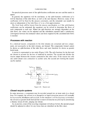
A reactor is represented as two units (Figure 4.10). The split-fractions for the first unit
are chosen to account for the loss of material by reaction. The second unit divides the
reactor output between the streams connected to the other units. If the reactor has only
one outlet stream (one connection to another unit), the second unit forming the reactor
can be omitted.
λ α Material
1k 01K
consumed
λ 1k λ
1 2k 2 λ α
2k j2k
g
20k
Material λ (1-α 01k )
1k
formed
Figure 4.10. Reactor unit
Closed recycle systems
In some processes, a component may be recycled around two or more units in a closed
loop. For example, the solvent in an absorption or liquid extraction process will normally
be recovered by distillation and recycled. In this situation it will be necessary to introduce
the solvent as a pseudo fresh-feed and the to remove it from the recycle loop by introducing
a dummy stream divider, purging one stream.
As, in practice, some of the recycling component will always be lost, the amount purged
should be adjusted to allow for any losses that are identified on the flow-sheet.