
Page 199 - Chemical engineering design
P. 199
176
CHEMICAL ENGINEERING
4.6.2. Illustration of the method
The procedure for setting up the equations and assigning suitable values to the split-
fraction coefficients is best illustrated by considering a short problem: the manufacture of
acetone from isopropyl alcohol.
Process description
heat
Reaction: C 3 H 7 OH ! CH 3 2 CO C H 2
cat.
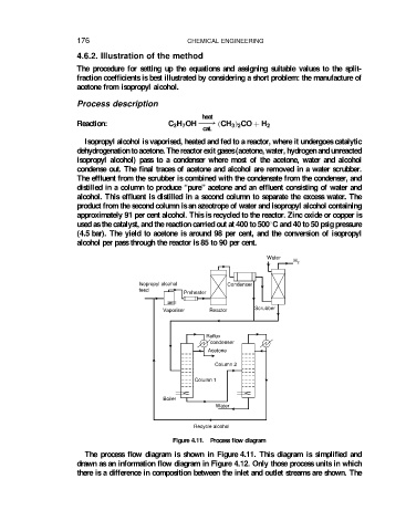
Isopropyl alcohol is vaporised, heated and fed to a reactor, where it undergoes catalytic
dehydrogenation to acetone. The reactor exit gases (acetone, water, hydrogen and unreacted
isopropyl alcohol) pass to a condenser where most of the acetone, water and alcohol
condense out. The final traces of acetone and alcohol are removed in a water scrubber.
The effluent from the scrubber is combined with the condensate from the condenser, and
distilled in a column to produce “pure” acetone and an effluent consisting of water and
alcohol. This effluent is distilled in a second column to separate the excess water. The
product from the second column is an azeotrope of water and isopropyl alcohol containing
approximately 91 per cent alcohol. This is recycled to the reactor. Zinc oxide or copper is
Ž
used as the catalyst, and the reaction carried out at 400 to 500 C and 40 to 50 psig pressure
(4.5 bar). The yield to acetone is around 98 per cent, and the conversion of isopropyl
alcohol per pass through the reactor is 85 to 90 per cent.
Water
H 2
Isopropyl alcohol Condenser
feed
Preheater
Vaporiser Reactor Scrubber
Reflux
condenser
Acetone
Column 2
Column 1
Boiler
Water
Recycle alcohol
Figure 4.11. Process flow diagram
The process flow diagram is shown in Figure 4.11. This diagram is simplified and
drawn as an information flow diagram in Figure 4.12. Only those process units in which
there is a difference in composition between the inlet and outlet streams are shown. The