
Page 212 - Chemical process engineering design and economics
P. 212
Compressors, Pumps, and Turbines 195
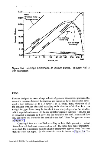
Note:
One-stage pump
Two-stage pump
___• • i i i i i ii___i i i i i 1 1 1 i i i , "rf
1
1 2 4 6 T O 2 0 4 0 6 0 1 0 0 2 0 0 4 0 0 t
600
Pressure, ton
Figure 5.4 Isentropic Efficiencies of vaccum pumps. (Source Ref. 3
with permission)
FANS
Fans are designed to move a large volume of gas near atmospheric pressure. Be-
cause the clearance between the impeller and casing are large, the pressure devel-
oped is low, between 1.01 to 1.15 bar (14.7 to 16.7 psia). Fans, which are all of
the dynamic type, are classified according to the direction of air flow. In a cen-
trifugal fan, gas flows along the fan shaft, turns ninety degrees by the impeller,
which imparts kinetic energy to the gas as it flows radially outward. Then, the gas
is converted to pressure as it leaves the fan parallel to the shaft. In an axial flow
fan, gas enters and leaves the fan parallel to the shaft. These fan types are shown
in Figure 5.5.
Centrifugal fans are classified according to their blade geometry - radial,
forward curved, backward curved, and air foil. The radial fan's major characteris-
tic is its ability to compress gases to a higher pressure but delivers lower flow rates
than the other fan types. Its characteristic curve is shown in Figure 5.6. The
Copyright © 2003 by Taylor & Francis Group LLC