
Page 215 - Chemical process engineering design and economics
P. 215
198 Chapters
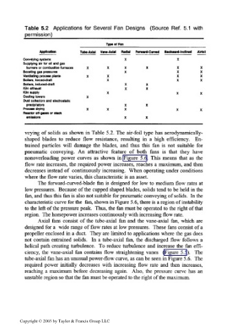
Table 5.2 Applications for Several Fan Designs (Source Ref. 5.1 with
permission)
Typcef Fan
Application Tuba-Axial Vane-Axial Radial Forward-Curved Backward-Inclined Airfoil
Conveying systems X X
Supplying air for oil and gas
burners or combustion furnaces X X X X X X
Boosting gas pressures X X X
Ventilating process plants X X X X
Boilers, forced-draft X X X
Boilers, induced-draft X X
Kiln exhaust X X
Kiln supply X X X
Cooling towers X
Dust collectors and electrostatic
predpitators X X
Process drying X X X X X
Reactor off-gases or stack
emissions X X
veying of solids as shown in Table 5.2. The air-foil type has aerodynamically-
shaped blades to reduce flow resistance, resulting in a high efficiency. En-
trained particles will damage the blades, and thus this fan is not suitable for
pneumatic conveying. An attractive feature of both fans is that they have
nonoverloading power curves as shown in Figure 5.6. This means that as the
flow rate increases, the required power increases, reaches a maximum, and then
decreases instead of continuously increasing. When operating under conditions
where the flow rate varies, this characteristic is an asset.
The forward-curved-blade fan is designed for low to medium flow rates at
low pressures. Because of the cupped shaped blades, solids tend to be held in the
fan, and thus this fan is also not suitable for pneumatic conveying of solids. In the
characteristic curve for the fan, shown in Figure 5.6, there is a region of instability
to the left of the pressure peak. Thus, the fan must be operated to the right of that
region. The horsepower increases continuously with increasing flow rate.
Axial fans consist of the tube-axial fan and the vane-axial fan, which are
designed for a wide range of flow rates at low pressures. These fans consist of a
propeller enclosed in a duct. They are limited to applications where the gas does
not contain entrained solids. In a tube-axial fan, the discharged flow follows a
helical path creating turbulence. To reduce turbulence and increase the fan effi-
ciency, the vane-axial fan contains flow straightening vanes (Figure 5.5). The
tube-axial fan has an unusual power-flow curve, as can be seen in Figure 5.6. The
required power initially decreases with increasing flow rate and then increases,
reaching a maximum before decreasing again. Also, the pressure curve has an
unstable region so that the fan must be operated to the right of the maximum.
Copyright © 2003 by Taylor & Francis Group LLC