
Page 265 - Chemical process engineering design and economics
P. 265
Compressors, Pumps, and Turbines 245
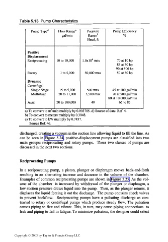
Table 5.13 Pump Characteristics
Pump Type" Flow Range 3 Pressure Pump Efficiency
gal/min Range b %
Head, ft
Positive
Displacement
s
Reciprocating 10 to 10,000 1.0xlO max 70 at 10 hp
85 at 50 hp
90 at 500 hp
Rotary 1 to 5,000 50,000 max 50 at 80 hp
Dynamic
Centrifugal
Single Stage 15 to 5,000 500 max 45 at 100 gal/min
Multistage 20 to 11, 000 5,500 max 70 at 500 gal/min
80 at 10,000 gal/min
Axial 20 to 100,000 40 65 to 85
a) To convert to rrrVmin multiply by 0.003785. d) Source of data: Ref 4.
b) To convert to meters multiply by 0.3048.
c) To convert to kW multiply by 0.7457.
Source Ref. 46.
discharged, creating a vacuum in the suction line allowing liquid to fill the line. As
can be seen in Figure 5.24, positive-displacement pumps are classified into two
main groups: reciprocating and rotary pumps. These two classes of pumps are
discussed in the next two sections.
Reciprocating Pumps
In a reciprocating pump, a piston, plunger or diaphragm moves back-and-forth
resulting in an alternating increase and decrease in the volume of the chamber.
Examples of common reciprocating pumps are shown in Figure 5.25. As the vol-
ume of the chamber is increased by withdrawal of the plunger or diaphragm, a
low suction pressure draws liquid into the pump. Then, as the plunger returns, it
displaces the liquid forcing it out the discharge. The pump contains check valves
to prevent backflow. Reciprocating pumps have a pulsating discharge as con-
trasted to rotary or centrifugal pumps which produce steady flow. The pulsation
causes piping to flex and vibrate. This, in turn, may cause piping connections to
leak and piping to fail in fatigue. To minimize pulsation, the designer could select
Copyright © 2003 by Taylor & Francis Group LLC