
Page 262 - Chemical process engineering design and economics
P. 262
242 Chapter 5
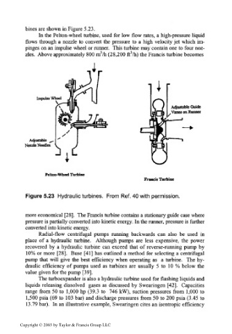
bines are shown in Figure 5.23.
In the Pelton-wheel turbine, used for low flow rates, a high-pressure liquid
flows through a nozzle to convert the pressure to a high velocity jet which im-
pinges on an impulse wheel or runner. This turbine may contain one to four noz-
3
3
zles. Above approximately 800 m /h (28,200 ft /h) the Francis turbine becomes
Impulse Wheel
Adjustable Guide
, Vanes on Runner
Adjustable __
Nozzle Needles
Pelton-Wheel Turbine
Francis Turbine
Figure 5.23 Hydraulic turbines. From Ref. 40 with permission.
more economical [28]. The Francis turbine contains a stationary guide case where
pressure is partially converted into kinetic energy. In the runner, pressure is further
converted into kinetic energy.
Radial-flow centrifugal pumps running backwards can also be used in
place of a hydraulic turbine. Although pumps are less expensive, the power
recovered by a hydraulic turbine can exceed that of reverse-running pump by
10% or more [28]. Buse [41] has outlined a method for selecting a centrifugal
pump that will give the best efficiency when operating as a turbine. The hy-
draulic efficiency of pumps used as turbines are usually 5 to 10 % below the
value given for the pump [39].
The turboexpander is also a hydraulic turbine used for flashing liquids and
liquids releasing dissolved gases as discussed by Swearingen [42]. Capacities
range from 50 to 1,000 hp (39.3 to 746 kW), suction pressures from 1,000 to
1,500 psia (69 to 103 bar) and discharge pressures from 50 to 200 psia (3.45 to
13.79 bar). In an illustrative example, Swearingen cites an isentropic efficiency
Copyright © 2003 by Taylor & Francis Group LLC