
Page 326 - Chemical process engineering design and economics
P. 326
Separator Design 305
is usually divided into 12 to 24 longitudinal compartments [25], depending on the
drum diameter. Each compartment contains channels for collecting liquid that
flows into filtrate piping, which leads to the filter valve at one end of the drum. A
vacuum can be applied separately to each compartment. The drum is partially
submerged in a slurry tank, which contains an agitator to prevent solids from set-
tling. Usually, the slurry tank is designed to submerge about 40% of the drum
area, but the maximum effective submerged filter area that can be subjected to
vacuum is about 37.5%. As the drum rotates, each compartment is connected to
an external system by the filter valve to apply vacuum, to collect filtrate, to collect
wash water, or to apply air pressure to assist in removing solids from the drum.
The operation of a rotary-drum filter can be followed by examining Figure
6.9. In the cake-forming zone, slurry is drawn from the slurry tank onto the drum
by a vacuum, depositing solids on the drum. After leaving this zone, the cake is
dewatered, washed, if it is necessary, and then dewatered again before being dis-
charged. In one method of cake removal, compressed air pushes the filter cloth
against a knife that scrapes the cake from the cloth. The cake could also be re-
moved by a roll, string or belt, depending on the cake thickness.
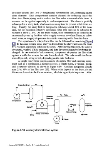
A simple rotary-filter system consists of a rotary filter and auxiliary equip-
ment such as a compressor, a filtrate receiver, a filtrate pump, a vacuum pump,
and a separator-silencer, as shown in Figure 6.10. Auxiliary equipment usually
runs 25 to 40% of the filter cost [25]. When solids deposit on the drum, air and
filtrate are drawn into the filtrate receiver, which is a gas-liquid separator. After
Knock-Out Drum Air
Compressor
Slurry ^r Water
Filtrate
Pump
Figure 6.10 A rotary-drum filtration system.
Copyright © 2003 by Taylor & Francis Group LLC