
Page 337 - Chemical process engineering design and economics
P. 337
316
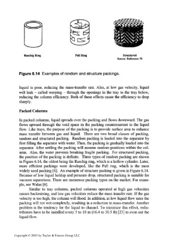
Raschig Ring Pall Ring Structured
Source: Reference 78
Figure 6.14 Examples of random and structure packings.
liquid is poor, reducing the mass-transfer rate. Also, at low gas velocity, liquid
will leak - called weeping - through the openings in the tray to the tray below,
reducing the column efficiency. Both of these effects cause the efficiency to drop
sharply.
Packed Columns
In packed columns, liquid spreads over the packing and flows downward. The gas
flows upward through the void space in the packing countercurrent to the liquid
flow. Like trays, the purpose of the packing is to provide surface area to enhance
mass transfer between gas and liquid. There are two broad classes of packing,
random and structured packing. Random packing is loaded into the separator by
first filling the separator with water. Then, the packing is gradually loaded into the
separator. After settling the packing will assume random positions within the col-
umn. Also, the water prevents breaking fragile packing. For structured packing,
the position of the packing is definite. Three types of random packing are shown
in Figure 6.14, the oldest being the Raschig ring, which is a hollow cylinder. Later,
more efficient packings were developed, like the Pall ring, which is the most
widely used packing [6]. An example of structure packing is given in Figure 6.14.
Because of low liquid holdup and pressure drop, structured packing is suitable for
vacuum separations. There are numerous packing types on the market. For exam-
ple, see Walas [6].
Similar to tray columns, packed columns operated at high gas velocities
causes backmixing, and low gas velocities reduce the mass transfer rate. If the gas
velocity is too high, the column will flood. In addition, at low liquid flow rates the
packing will not wet completely, resulting in a reduction in mass-transfer. Another
problem is the tendency for the liquid to channel. To minimize this effect, redis-
tributors have to be installed every 5 to 10 m (16.4 to 30.5 ft) [23] to even out the
liquid flow.
Copyright © 2003 by Taylor & Francis Group LLC