
Page 338 - Chemical process engineering design and economics
P. 338
Separator Design 317
90
^ 80
I™
^j 60
I 50
40
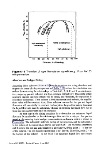
High weeping and Normal operating range
poor mixing
High attainment
I
10 20 30 40 50 60 70 80 90 100
Flowrate, % of Rending
Figure 6.15 The effect of vapor flow rate on tray efficiency. From Ref. 33
with permission.
Absorber and Stripper Sizing
Assuming dilute solutions, Table 6.21 lists the equations for sizing absorbers and
strippers in terms of a key component and Table 6.22 outlines the calculation pro-
cedure. In numbering the relationships in Table 6.21, A, S, P, and T means absorp-
tion, stripping, packed columns and tray columns, respectively. Processing dilute
solutions implies that heat effects will be small, and therefore, the separation is
essentially isothermal. If the column is both isothermal and isobaric, the equilib-
rium value will be constant. Also, dilute solution means that the gas and liquid
flow rates will essentially be constant. In absorption, the gas flow rate is fixed and
the liquid flow rate must be estimated, whereas in stripping the liquid flow rate is
fixed and the gas flow rate must be estimated.
The first step in the sizing procedure is to determine the minimum liquid
flow rate for an absorber or the minimum gas flow rate for a stripper. For gas ab-
sorption, the entering liquid and gas concentrations are known, which is shown in
Figure 6.16. The subscript 1 refers to the top of the separator, and the subscript 2
to the bottom of the separator, as shown in Figure 6.16. The fractional absorption
and therefore the exit gas concentration is also known, fixing point 1 - at the top
of the column. The exit liquid concentration is not known. Therefore, point 2 - at
the bottom of the column - is not fixed. The minimum liquid flow rate occurs
Copyright © 2003 by Taylor & Francis Group LLC