
Page 476 - Chemical process engineering design and economics
P. 476
454 Chapter 8
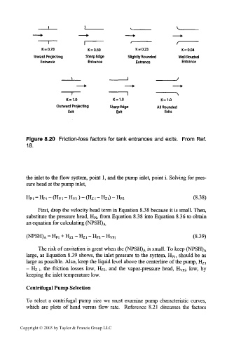
K=0.78 K = 0.50 K = 0.23 K = 0.04
Inward Projecting Sharp Edge Slightly Rounded WellRouded
Entrance Entrance Entrance Entrance
K=1.0 K=1.0 K=1.0
Outward Projecting Sharp Edge All Rounded
Exit Exit Exits
Figure 8.20 Friction-loss factors for tank entrances and exits. From Ref.
18.
the inlet to the flow system, point 1, and the pump inlet, point i. Solving for pres-
sure head at the pump inlet,
Hpj = Hpi - (Hyi - Hyi) - (H z; - HZI) - HFS (8.38)
First, drop the velocity head term in Equation 8.38 because it is small. Then,
substitute the pressure head, H Pi, from Equation 8.38 into Equation 8.36 to obtain
an equation for calculating (NPSH) A.
(8.39)
(NPSH) A = H P1 + H zl -H zi -H FS -H V p i
The risk of cavitation is great when the (NPSH) A is small. To keep (NPSH) A
large, as Equation 8.39 shows, the inlet pressure to the system, H P1, should be as
large as possible. Also, keep the liquid level above the centerline of the pump, H Z1
- HZ j, the friction losses low, H FS, and the vapor-pressure head, Hypj, low, by
keeping the inlet temperature low.
Centrifugal Pump Selection
To select a centrifugal pump size we must examine pump characteristic curves,
which are plots of head versus flow rate. Reference 8.21 discusses the factors
Copyright © 2003 by Taylor & Francis Group LLC