Page 481 - Chemical process engineering design and economics
P. 481
458                                                       Chapter 8

           are  known.  The  pump  will  supply  the  work  to transfer  the  water from  the  liquid
           surface  in the  feed  tank to  the  liquid surface  in the boiler.  From Equation 8.33,
           calculate  the  pump  work  as  the  difference  of  the  pump  discharge  and  suction
           heads.  Both heads  are  the  sum  of  the  velocity, elevation, pressure,  and  friction
           heads. Divide the calculation into two parts. First, calculate the  suction head, and
           then calculate the discharge head.
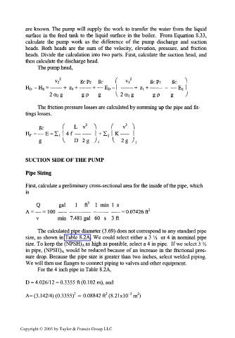
                The pump head,

                        2                        2
                      v 2      gcP2   gc    (  v,       gcpi    g c  "\
           H D -H S = ——— +  z 2 + ——— + — E D-  ——— +  zi + ——— -  — E s  I
                    2 cc 2 g    gp    g     I  2 a 2 g   gp    g    )

                The friction pressure losses are calculated by summing up the pipe and fit-
           tings losses.

                gc       (   L  v 2  ^    (   v 2  ^
           H F =_E  = I; | 4f — ——  I Zj  | K ——  |
                                     +
                g        I  D  2g  )i    I  2g  Jj


           SUCTION SIDE OF THE PUMP

           Pipe Sizing

           First, calculate a preliminary cross-sectional area for the inside of the pipe, which
           is

               Q       gal   1   ft 3  1  min  1  s
           A = — =100  —— —————     ———   —— = 0.07426 ft 2
               v       min  7.481  gal  60  s  3 ft

                The calculated pipe diameter (3.69) does not correspond to any standard pipe
           size,  as shown in Table 8.2A.  We  could select either a 3  Vi  or 4 in nominal pipe
           size. To keep the (NPSH) Aas high as possible, select a 4 in pipe.  If we select 3  '/•>
           in pipe,  (NPSH) A would be reduced because of an increase in the  frictional  pres-
           sure drop. Because the pipe size is greater than two inches, select welded piping.
           We will then use flanges to connect piping to valves and other equipment.
                For the 4 inch pipe in Table 8.2A,

           D = 4.026/12 = 0.3355 ft (0.102 m), and

                                         2
                                                 3
                                                    2
                             2
           A= (3.142/4) (0.3355)  =  0.08842 ft  (8.21xlO~  m )


         Copyright © 2003 by Taylor & Francis Group LLC

