
Page 484 - Chemical process engineering design and economics
P. 484
Design of Flow Systems 461
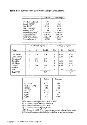
Table 8.4.1 Summary of Flow-System Design Computations.
Suction Discharge
Flow Rate (gal/min) a 100 100
3 b
Density (Ib/ft ) 62.3 62.3
Pipe ID (ft) c 0.336 0.256
Pipe Length (ft) c 12.0 60.0
Velocity (ft/s) d 2.84 4.34
Viscosity (lb M/ft-s) d 6.60x10-" 6.60x1 0- 4
Reynolds Number S.OxlO 4 l.OSxlO 5
Relative Roughness 5.89x10"* 5.89x10^
Friction Factor, 4f 0.0205 0.021
Suction (4 in pipe) Discharge (3 in pipe)
Fitting No. K Total K No. K Total K
Gate Valves 1 0.16 0.16 3 0.20 0.60
Check Valves 1 2.00 2.00
Tees, Branch 1 0.67 0.67
3
Tees, Line 1 0.13 0.130.16 0.48
90° Elbows 1 0.33 0.33
Flanges 6 2 0.04 0.08 4 0.04 0.16
Entrance 1 0.23 0.23
Exit 1 1.00 1.0
Total (IK) 1.27 4.57
Suction Discharge
1(4 f L/D) 0.732 4.92
l.l[I(4fL/D)] 8.05 5.41
1.25 IK 1.59 5.71
2
v /2g (ft) d 0.125 0.292
H F' (ft)" 0.299 3.25 f
H z(ft) d 7.0 49.0
H P(ft) d 34.0 115.0
3
3
a) To convert to m /min multiply by 3.785xlO~ .
3
b) To convert to kg/m multiply by 16.019.
c) To convert to m multiply by 0.3048.
d) To convert to m/s multiply by 0.3048.
e) No data are available. Use a union to approximate a flanged connection.
f) Frictional losses do not include the control valve and heat exchanger.
Copyright © 2003 by Taylor & Francis Group LLC